
Welding electrode and method

Active Publication Date: 2006-11-23
HUYS IND
View PDF33 Cites 24 Cited by
  • Summary
  • Abstract
  • Description
  • Claims
  • Application Information

AI Technical Summary

Benefits of technology

[0009] In a feature of that aspect of the invention, the electrode has a predominantly titanium coating formed thereon. In another feature, that coating has first and second layers. In another feature, the first and second layers are composed predominantly of titanium carbide, and the second layer has a higher weight percentage of titanium carbide than does the first layer. In another feature, the first layer has a higher weight percentage

Problems solved by technology

The electrical resistance presented at the interface between the workpieces may tend to cause local heating to occur, with the result that the workpieces fuse locally to form a weld nugget.
One cause of interruption may be the need to replace electrodes from time to time.
As may be expected, the electrodes may tend to be come hot during use.
The elevated temperature may be associated with a number of phenomena tending to shorten electrode life or to degrade welding performance, or both.
First, the electrodes may tend to “pick up”, or stick, to the workpiece with the result that sparking and weld separation may occur as the electrodes are removed.
Second, the elevated temperatures may be such as to soften the copper electrodes, making them more prone to deformation under the applied contact pressure during welding.
Third, inasmuch as the welding electrodes in question may frequently be used to spot weld galvanized steel sheet in the manufacture of automobiles, at welding temperatures the zinc from the galvanized sheet may tend to migrate into the copper of the welding electrode, this tendency being greatest at the contact region of the electrode.
This may tend, undesirably, to cause the formation of brass alloys at the electrode tip, and may tend to shorten tip life.
Over time, a coating on an electrode tip may tend to degrade under the impact when the welding heads are closed onto the workpiece, in consequence of the heating, and in consequence of the chemical environment.
The coating may be worn away, or may become cracked, and the electrode may approach the end of its useful life.

Method used


Image

  • Welding electrode and method
  • Welding electrode and method
  • Welding electrode and method

Examples


Embodiment Construction

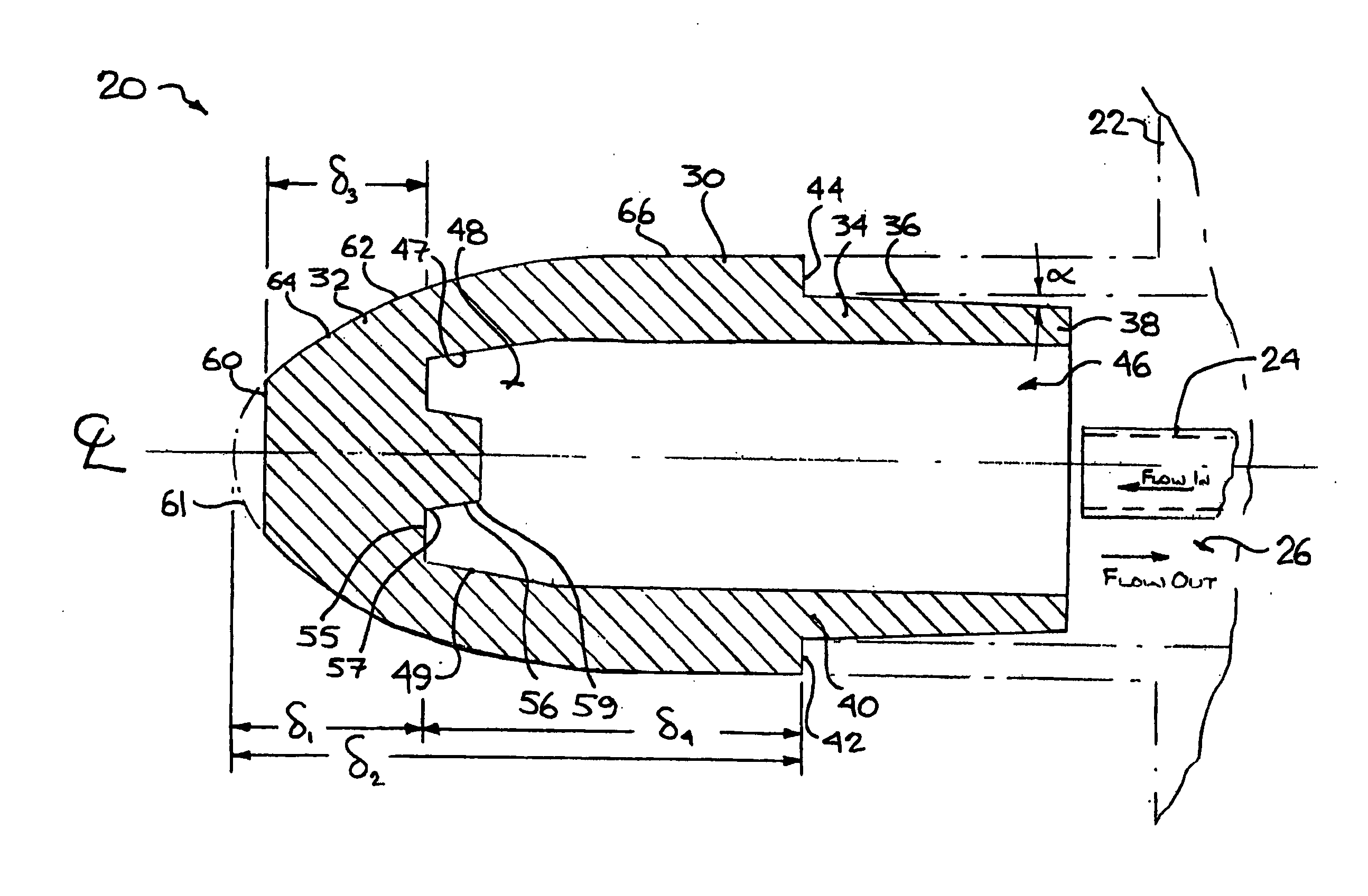
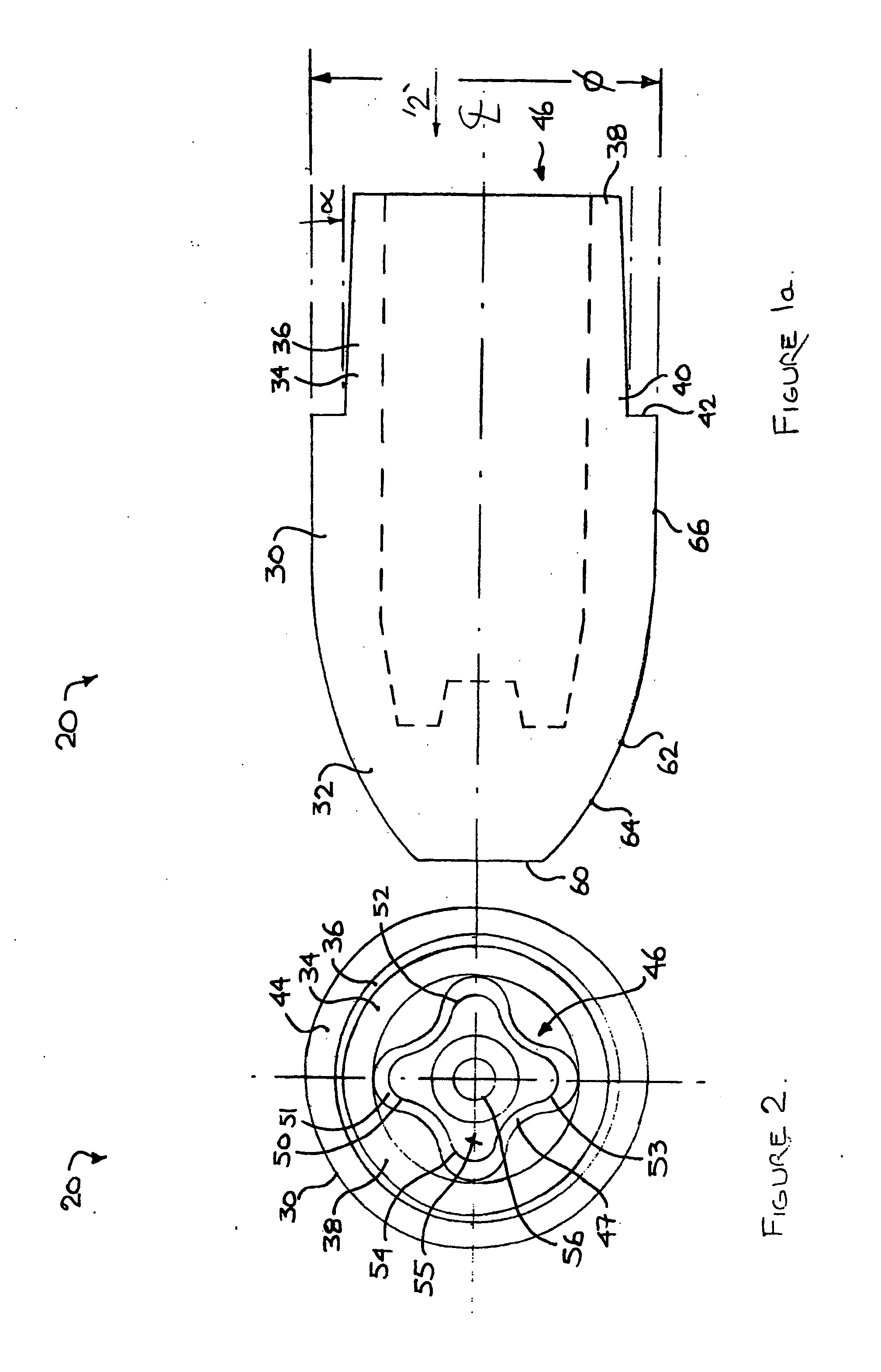
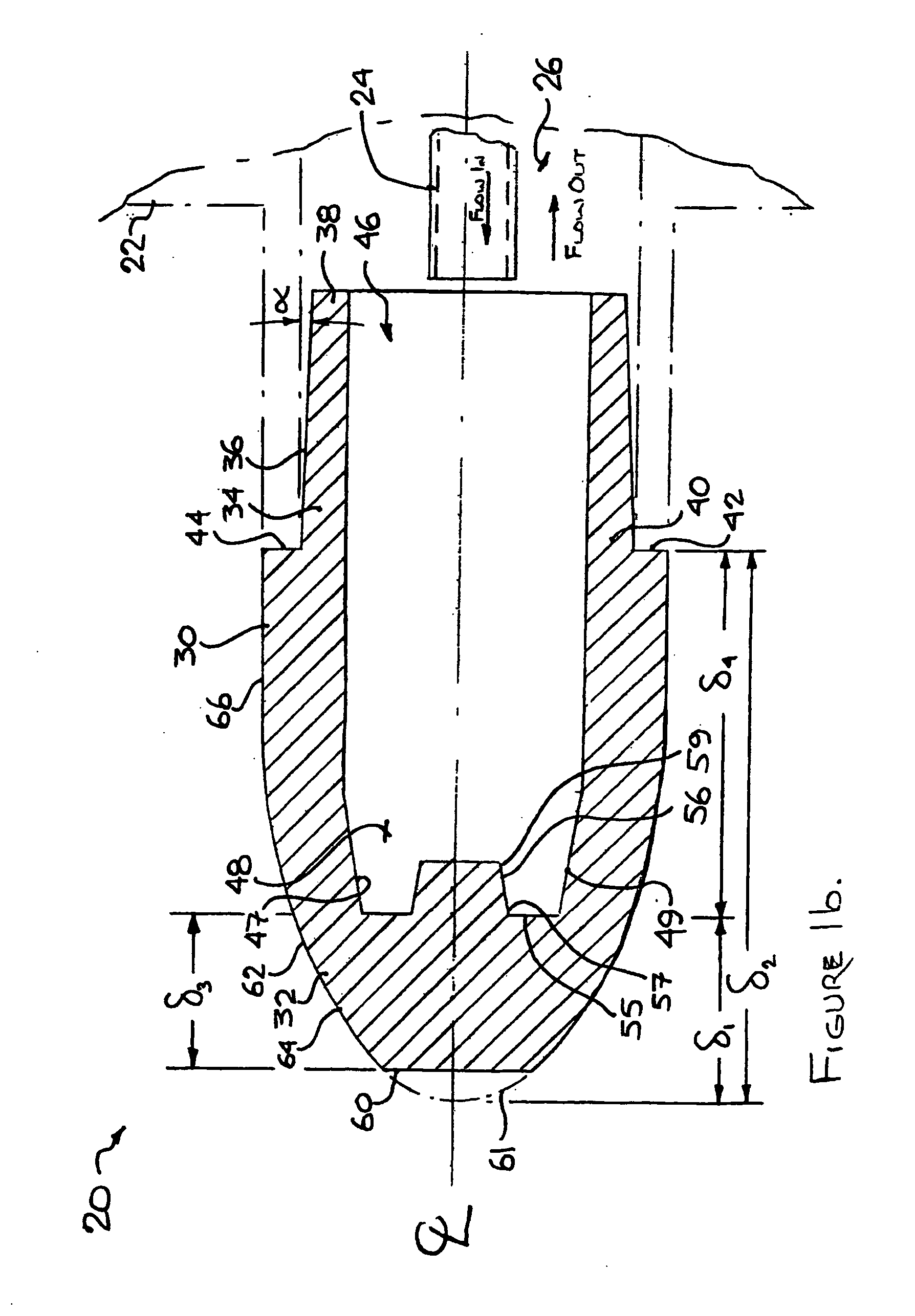
[0032] The description that follows, and the embodiments described therein, are provided by way of illustration of an example, or examples, of particular embodiments of the principles of aspects of the present invention. These examples are provided for the purposes of explanation, and not of limitation, of those principles and of the invention. In the description, like parts are marked throughout the specification and the drawings with the same respective reference numerals. The drawings are not necessarily to scale and in some instances, proportions may have been exaggerated in order more clearly to depict certain features of the invention.

[0033] In this description, a welding electrode may be of either the male type or the female type, as described below. In either case, the welding electrode may have the general form of a body of revolution formed about a central axis. This body of revolution may be considered in terms of a polar cylindrical co-ordinate system having a long axis...


PUM

PropertyMeasurementUnit
Angleaaaaaaaaaa
Weightaaaaaaaaaa
Compositionaaaaaaaaaa

Abstract

A welding electrode has a body having a shank and a contact region for placement against a workpiece during welding. A portion of the body may be formed on a parabolic profile. A coating is formed on the contact region. The coating may have a first layer, and a second layer formed over the first layer. The first and second layers may have different compositions. The electrode may have internally formed cooling finwork for interaction with a liquid cooling system.

Description

FIELD OF THE INVENTION [0001] This invention relates to the field of welding electrodes. BACKGROUND OF THE INVENTION [0002] Welding electrodes may be used in electric resistance welding. Resistance welding techniques are widely used in industry, an example of one such use being the spot welding of car bodies. In that particular application, a welding gun fitted with a pair of co-operating electrodes may be moved in steps along a weld path. At each step, the electrodes are closed onto opposite sides of the workpieces to be welded and an electric current is passed between the electrodes. The electrical resistance presented at the interface between the workpieces may tend to cause local heating to occur, with the result that the workpieces fuse locally to form a weld nugget. The electrodes are then removed from the workpieces. On a production line basis, these steps are performed in rapid sequence and are repeated at each successive weld location. [0003] In high volume manufacturing, p...

Claims


Application Information

Patent Timeline
IPC IPC(8): B23K11/30
CPCB23K11/3009H05H2001/3478H05H2001/3436H05H1/34H05H1/3436H05H1/3478
Inventor SCOTCHMER, NIGEL
Owner HUYS IND
Learn More