Apparatus and method for generating a complementary cumulative distribution function (CCDF) curve

a cumulative distribution and curve technology, applied in the field of appratus and method for generating a complementary cumulative distribution function (ccdf) curve, can solve the problems of ten samples, high distortion, and missing the elusive high peak level, and achieve the effect of reducing length and shortening bit length data words

Active Publication Date: 2006-11-16
KEYSIGHT TECH
View PDF2 Cites 2 Cited by
  • Summary
  • Abstract
  • Description
  • Claims
  • Application Information

AI Technical Summary

Benefits of technology

[0016] The apparatus may further comprise a comparator having a first input for receiving a received parameter value on the first clock cycle and a second input for receiving a next received parameter value on the second clock cycle and an output for providing a match signal if the received parameter value and the next received parameter value are the same, the output of the comparator being coupled to the dual port memory and the match signal being utilised to enable the first port of the dual port memory to be utilised as the input for the second clock cycle so that the frequency count incremented on the first clock cycle is provided at the first port instead of the second port and is therefore correctly provided to the input of the adder on the second clock cycle.
[0019] The memory elements may accept shorter bit length data words than the bit length of data words received from the ADC, and the multiplexer may pass a reduced length of each parameter value data word received from the ADC to one of the plurality of outputs based on the most significant data bits that are present in the parameter value data word received from the ADC.

Problems solved by technology

This signal characteristic can lead to higher distortion unless the peak power levels are accounted for in the design of system components, such as amplifiers and mixers.
What this means is that a typical system will take very short snapshots of a waveform, which can result in missing the elusive high peak levels that have the greatest effect on the resulting measurement numbers.
Furthermore, ten samples is, in some circumstances, not a sufficiently large number on which to base an accurate measurement.

Method used


Image

  • Apparatus and method for generating a complementary cumulative distribution function (CCDF) curve
  • Apparatus and method for generating a complementary cumulative distribution function (CCDF) curve
  • Apparatus and method for generating a complementary cumulative distribution function (CCDF) curve

Examples


second embodiment

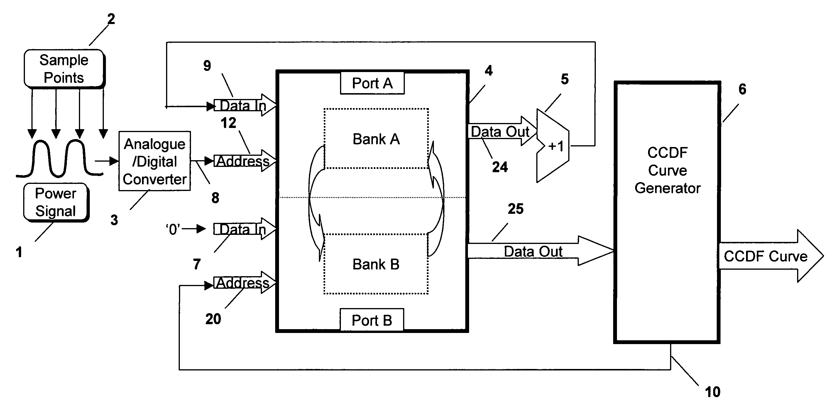
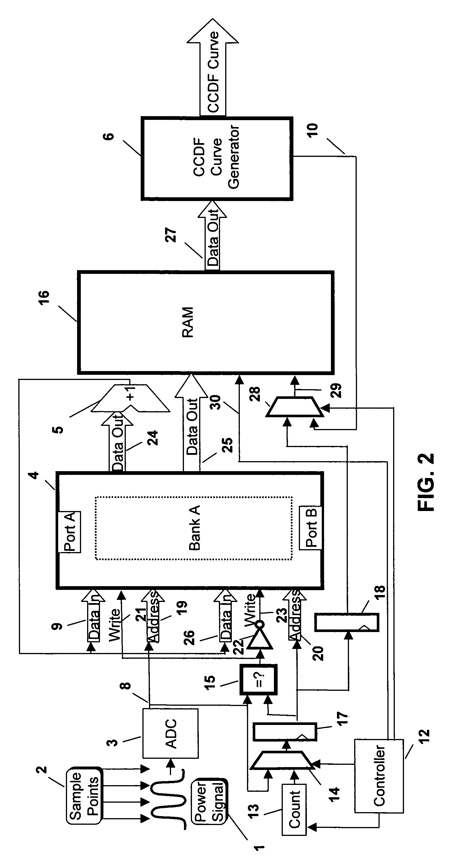
[0036] Both problems are overcome in the invention, which will now be described with reference to FIG. 2, where the same elements as those in FIG. 1 are designated using the same numerals for ease of reference. In this embodiment, in order to allow the data to be read out to the CCDF curve generator 6, the capture is halted for a short period of time periodically to allow the memory to be read out using one of the ports. The apparatus includes a controller 12 which is used to control a counter 13 for presenting a count value to a first multiplexer 14. The controller 12 sets the counter to count down from one of two possible counts so as to have, effectively, two different time periods. During a first, longer, time period, the apparatus is used in “data capture” mode to capture the required data to the memory 4 and in the second, shorter, time period, the apparatus is used in “read” mode to read the contents of the memory 4 out to a second memory 16.

[0037] Thus, the output 8 of the A...

first embodiment

[0038] If the apparatus is in the “read” mode, then the controller 12 controls the multiplexer 14 to pass the count value from the counter 13 to its output. This count value is used as the address at the address input 20 of Port B of the memory 4 and the contents of that address in the memory is read out at data output 25 to the second memory 16. Clearly, therefore, as the counter 13 cycles through all the count values, each address is read out to the second memory 16 and when the counter 13 times out, all the addresses have been read and the counter is again initialised by the controller to count the time period for the “data capture” mode. If desired, as the addresses are read out to the second memory 16, the data can be set to zero, as described above with reference to the

[0039] As long as the apparatus is in the “data capture” mode, the comparator 15 receives the address from the ADC at its first input and the address from the ADC from the previous clock cycle, which has been pa...

third embodiment

[0045]FIG. 4 shows the present invention, where, again, the same elements as in the previous embodiments are designated with the same numerals for ease of reference. In this case, as can be seen, the memory 4, the second memory 16, and some of the circuit elements including the first latch 17 and the comparator 15, form a histogram capturing block 42. In this embodiment, a data word 43 from the ADC output 8 is passed to a third multiplexer 44, which is used to pass a selected number of bits of the data word through to a third latch 45. The output of this third latch 45 provides the address passed to the address input 19 of Port A of the memory 4, as well as to the first multiplexer 14 and to the first input of comparator 15, as in the previous embodiment.

[0046] In this embodiment, the apparatus includes a plurality of similar histogram capturing blocks 42, each having the same inputs and outputs as the one shown in FIG. 4. Each histogram capturing block 42 is used to capture data in...


PUM


Abstract

In apparatus for generating a Complementary Cumulative Distribution Function (CCDF) curve for an input signal, an analog to digital converter (ADC) samples the input signal at sampling points to provide a parameter value corresponding to a desired parameter of the input signal at each sampled point. A memory element provides a frequency count of occurrence of each received parameter value from an address in the memory corresponding to the received parameter value. An adder receives the frequency count, increments the count and provides the incremented count to an input of the memory element for writing back into the address corresponding to the received parameter value. A CCDF curve generating module reads the frequency count stored in the memory element corresponding to each parameter value and generates a CCDF curve therefrom.

Description

PRIORITY CLAIM [0001] Foreign priority rights under Title 35, United States Code Section 119, to Great Britain Application Number 0509857.9, filed May 13, 2005, are hereby claimed. [0002] This invention relates to an apparatus and method for generating a Complementary Cumulative Distribution Function (CCDF) curve, especially, though not exclusively, to such a CCDF curve for signal power, for example in Radio Frequency applications. BACKGROUND ART [0003] A power CCDF curve is frequently used in RF applications to provide critical information about the signals encountered in RF systems, for example in modern 3rd Generation (3G) digitally modulated radio systems. The power CCDF curve consists of a curve relating the percentage of time a radio signal spends at or above a particular power level. It is usually shown as a graph of the ratio of the instantaneous power to the average power against percentage of time that the signal power is at, or above, the power specified in the X axis. Bo...

Claims


Application Information

Patent Timeline
Patent Type & Authority Applications(United States)
IPC IPC(8): G06F19/00G06F17/18
CPCG11C7/16G06F17/18
Inventor JOHNSTONE, COLINBREAKENRIDGE, ERIC
Owner KEYSIGHT TECH
Why Eureka
Try Eureka