Eureka AIR delivers breakthrough ideas for toughest innovation challenges, trusted by R&D personnel around the world.

Fuel cell air supply system and control method

An air supply and fuel cell technology, applied in fuel cells, fuel cell additives, fuel cell heat exchange, etc., can solve the problem of undiscovered cathode air intake system, achieve clear control method, fast response speed, and reduce control difficulty Effect

Inactive Publication Date: 2018-06-15
PINGXIANG HUICHENG PRECISION MACHINERY & ELECTRONICS
View PDF12 Cites 28 Cited by
  • Summary
  • Abstract
  • Description
  • Claims
  • Application Information

AI Technical Summary

Problems solved by technology

At present, no patent has been found that considers and controls the cathode air intake system as a whole

Method used


Image

  • Fuel cell air supply system and control method
  • Fuel cell air supply system and control method
  • Fuel cell air supply system and control method

Examples


Embodiment Construction

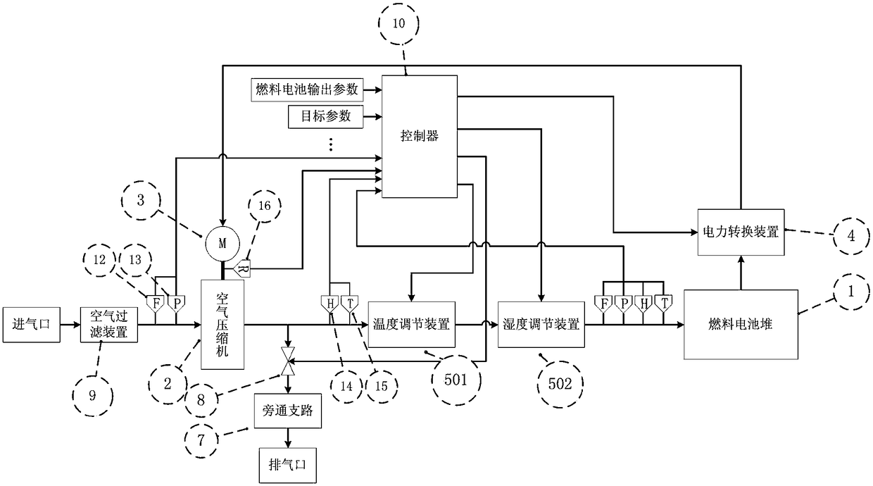
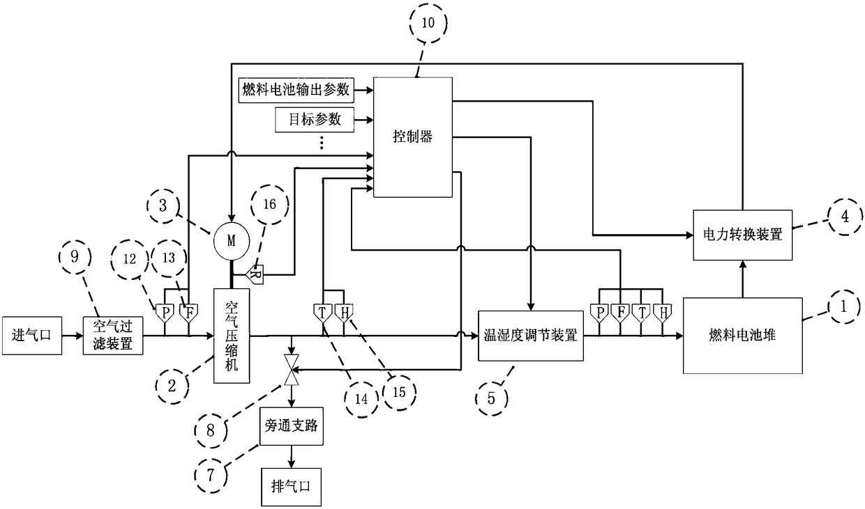
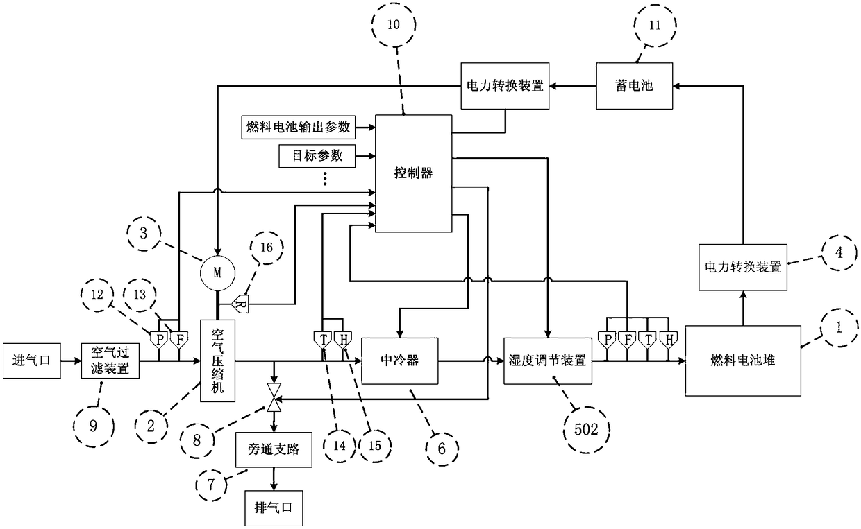
[0049] The technical solutions of the present invention will be described in further detail below with reference to the accompanying drawings and embodiments.

[0050] The present invention firstly provides a fuel cell air supply system, such as figure 1 As shown, the system includes:

[0051] a fuel cell stack 1 for generating electricity through an electrochemical reaction between an oxidant gas and a fuel gas;

[0052] an air compressor 2 for delivering air as an oxidant gas to the cathode of the fuel cell stack 1;

[0053] The motor 3 is connected with the air compressor 2 and is used to drive the air compressor 2 to work; the motor 3 and the air compressor 2 can be made as one;

[0054]The power conversion device 4 is connected between the fuel cell stack 1 and the motor 3, and is used to adjust the power supplied to the motor 3;

[0055] The temperature adjustment device 501 is connected between the air compressor 2 and the fuel cell stack 1, and is used to adjust the...


PUM


Abstract

The invention discloses a fuel cell air supply system. The fuel cell air supply system comprises a fuel cell pile used for performing power generation through an electrochemical reaction, an air compressor used for conveying air to the fuel cell pile, a motor used for driving the air compressor to work, an electric power conversion apparatus used for regulating the electric power supplied to the motor, a temperature regulation apparatus and a humidity regulation apparatus used for regulating the temperature and humidity of the supplied air to satisfy target parameters, a sensor assembly used for measuring the pressure, temperature, humidity and flow of the supplied air, and the rotary speed of the air compressor, a bypass branch used for discharging the residual air in the flow, a bypass valve used for controlling the starting area of the bypass branch, an air filtering apparatus used for filtering impurities from the supplied air, and a controller used for controlling operation of each module. By taking a negative electrode air inlet system as one integrated body to perform independent consideration and control, air with the most suitable parameters is supplied to the fuel cell pile accurately.

Description

technical field [0001] The invention relates to the technical field of fuel cells, in particular to a fuel cell air supply system and a control method. Background technique [0002] A fuel cell is an electrochemical device that relies on the electrochemical reaction between the oxidant gas of the cathode and the fuel gas of the anode to generate electricity. It is not limited by the efficiency of the Carnot cycle and can operate continuously for a long time when the reaction gas is sufficient. And no pollution, zero emissions. In recent years, the research on the application of fuel cell technology to various electric power equipment has attracted the attention of governments, enterprises and scientific research institutions of various countries. [0003] As one of the reactants, the cathode oxidant gas, its pressure, flow rate, temperature, humidity and other parameters have a direct impact on the performance of the entire fuel cell system. A fuel cell operating at high e...

Claims


Application Information

Patent Timeline
Patent Type & Authority Applications(China)
IPC IPC(8): H01M8/04089H01M8/04119H01M8/04007
CPCH01M8/04007H01M8/04089H01M8/04119Y02E60/50
Inventor 黄若陈辉张磊殷鹏吴定宸王腾飞
Owner PINGXIANG HUICHENG PRECISION MACHINERY & ELECTRONICS
Why Eureka
Eureka Blog
Learn More