Section steel and wall body using the section steel

a section steel and steel beam technology, applied in the direction of girders, walls, joists, etc., can solve the problems of insufficient bonding force, difficult to reduce the thickness of the wall, etc., to reduce the effect of preventing concrete displacement, reducing shearing stress, and reducing shearing area

Inactive Publication Date: 2006-11-09
JFE STEEL CORP +1
View PDF9 Cites 1 Cited by
  • Summary
  • Abstract
  • Description
  • Claims
  • Application Information

AI Technical Summary

Benefits of technology

[0009] Accordingly, a second object of the present invention is to obtain a wall having a reduced thickness.
[0073] Regarding h≦b1, when the projection lower-side width b1 is too small, the projections may deform and reduce the effect of preventing displacement of the concrete. Therefore, the width b1 is set to be at least equal to or larger than the projection height h.
[0074] The above description is given of the projection lower-side width b1. When the projection upper-side width b2 is too large, this also reduces the shearing area (reduces the shearing stress) with respect to the concrete. Therefore, it is necessary to impose a certain limitation to the width b2. However, this limitation does not need to be added because 4b2≦P is given in the above (2) as the restrictive expression for preventing the shearing stress τ2 from decreasing.

Problems solved by technology

By study, the present inventor found that, even when projections are provided on inner faces of a shaped steel beam, a sufficient bonding force cannot always be obtained depending on the size and arrangement of the projections.
However, in the wall shown in FIG. 27, it is difficult to reduce the thickness of the wall while maintaining the bearing force of the wall.

Method used


Image

  • Section steel and wall body using the section steel
  • Section steel and wall body using the section steel
  • Section steel and wall body using the section steel

Examples


first embodiment

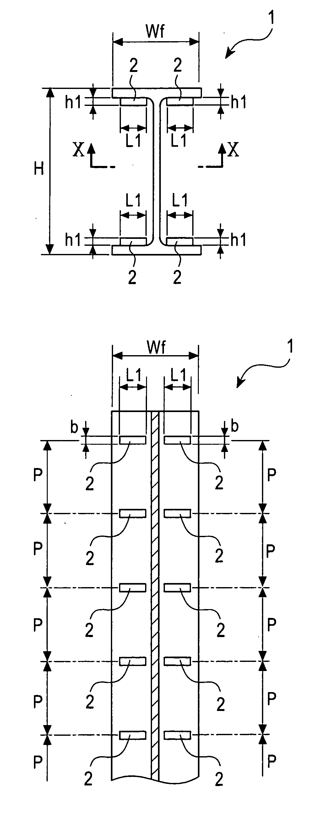
[0124] FIGS. 1(a) and 1(b) are explanatory views of an H-beam 1 with projections according to a first embodiment of the present invention. FIG. 1(a) is a schematic plan view, and FIG. 1(b) is a cross-sectional view taken along line X-X.

[0125] In the H-beam 1 with projections of the first embodiment, projections 2 of rectangular cross section are provided at a plurality of positions in the longitudinal direction of the H-beam on four inner faces of flanges so that the longitudinal direction of the projections coincides with the direction of the flange width Wf, as shown in FIGS. 1(a) and 1(b). The projections 2 on the flange inner faces have a projection height h1, a projection width b, and a projection length L1, and are not in contact with the corners defined by the flanges and a web.

[0126] Regarding the shape and arrangement of the projections, the projection pitch P is set to be within the range of 4b to 40h1, and the projection height h1 is set to be within the range of 2mm to...

second embodiment

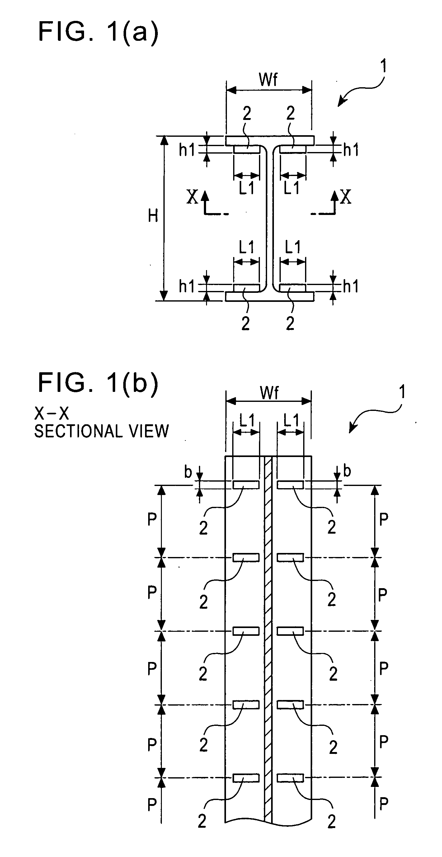
[0128] FIGS. 2(a) and 2(b) are explanatory views of an H-beam 11 with projections according to a second embodiment of the present invention, FIG. 2(a) is a schematic plan view, and FIG. 2(b) is a cross-sectional view taken along line X-X.

[0129] In the H-beam 11 with projections of the second embodiment, projections 2 of rectangular cross section are provided on four inner faces of flanges, in a manner similar to that in the projections 2 of the first embodiment, as shown in FIG. 2, and projections 2A serving as bonding-force increasing means are provided at a plurality of positions in the longitudinal direction of the H-beam on both surfaces of a web so that the longitudinal direction thereof coincides with the height direction of the web.

[0130] The projections 2A are provided on both surfaces of the web, and have a projection height h2, a projection width b, and a projection length L2. Both the projections 2 on the flange inner faces and the projections 2A on the web surfaces are...

third embodiment

[0133]FIG. 3 is an explanatory view of an H-beam 21 with projections according to a third embodiment of the present invention. In the H-beam 21 with projections of the third embodiment, projections 2 having a projection height h1, a projection width b, and a projection length L1 are provided on four inner faces of flanges, and projections 2B having a projection height h2, a projection width b, and a projection length L3 are provided on web surfaces, as shown in FIG. 3. Both the projections 2 on the flange inner faces and the projections 2B on the web surfaces are in contact with the corners defined by the flanges and the web, and the projections 2B are not provided at the centers of the web surfaces.

[0134] The above-described contact with the corners can further increase the bonding force with respect to concrete or solidification soil (composition effect). The projection length L3 of the projections 2B provided on the web surfaces of the H-beam 21 with projections in the third emb...


PUM

PropertyMeasurementUnit
heightaaaaaaaaaa
heightaaaaaaaaaa
heightaaaaaaaaaa

Abstract

An object of the present invention is to obtain a shaped steel beam having a strong bonding force with respect to concrete, and to obtain a wall with a reduced thickness. An H-beam has a plurality of projections on an inner face, and satisfies the conditions P / h≦10 and P / b2≧4, where b2 represents the upper-side width of the projections, h represents the projection height, and P represents the projection pitch in a cross section perpendicular to the inner face having the projections. A wall uses the H-beam as a structural member. In the wall, H-beams stand at a plurality of positions in the longitudinal direction of the wall with outer faces of flanges pointing toward the surface of the wall.

Description

TECHNICAL FIELD [0001] The present invention relates to a shaped steel beam that is applicable to the fields of civil engineering and construction, and to a wall using the shaped steel beam. BACKGROUND ART [0002] As a composite steel-concrete structure, for example, projections are provided on the surface of an H-beam, and concrete is provided around the H-beam. As such an H-beam with projections, an H-beam having projections on inner faces of flanges is known (for example, Japanese Examined Patent Application Publication No. 1-55042). [0003] As a wall using shaped steel beams as core materials, for example, an SRC wall using H-beams 101 is known, as shown in FIG. 27. The wall shown in FIG. 27 includes horizontal reinforcements 104 extending on both sides of concrete 103 in the horizontal direction of the wall, and main reinforcements 105 extending in the vertical direction of the wall so as to cross the horizontal reinforcements 104. H-beams 101 are provided in the center of the wa...

Claims


Application Information

Patent Timeline
Patent Type & Authority Applications(United States)
IPC IPC(8): E04H12/00E02D5/10E02D5/20E04B2/56E04C3/00E04C3/04E04C3/06E04C3/293E04C5/03
CPCE02D5/10E04C3/06E04C2003/0452E04C5/03E04C3/293E04B2/56E04B2/562E04B2/60
Inventor ONDA, KUNIHIKOTATSUMI, YUICHIWAKIYA, YASUSHIYAMAGUCHI, AKIRAISHIZAWA, TAKESHITAKEDA, ATSUSHIHIGASHINO, MITSUOHIRAO, JYUNICHIKAWAKAMI, TOSHINOBU
Owner JFE STEEL CORP
Why Eureka
Try Eureka