
Method and system of determining the absolute velocity of a vehicle

a technology of absolute velocity and vehicle, applied in the direction of time traversed devices, tyre measurements, devices using electric/magnetic means, etc., can solve the problems of inability to precisely determine the wheel radius, no standard sensors in commercial cars that can measure absolute velocity, and up to 10% error in velocity measuremen

Inactive Publication Date: 2006-10-26
NIRA DYNAMICS AB
View PDF7 Cites 13 Cited by
  • Summary
  • Abstract
  • Description
  • Claims
  • Application Information

AI Technical Summary

Benefits of technology

The invention is about a method, system, and computer program for determining the velocity of a vehicle with front and rear wheels that are spaced by a certain distance. The method involves measuring the speed of each wheel and correlating them to determine the time delay between the front and rear wheels. This correlation feature is then used to determine the vehicle's velocity based on the wheel spacing. The technical effect of this invention is to provide a more accurate and reliable method for determining the velocity of a vehicle with front and rear wheels.

Problems solved by technology

There are no standard sensors in commercial cars that can measure absolute velocity.
Wheel radii, however, may change with temperature, wear and even with the velocity to be measured due to centripetal forces which makes it impossible to exactly determine the wheel radius.
Thus, in practice only a nominal approximate value can be used which leads to up to 10% error in the velocity measurement.
While being very accurate and insensitive to wheel grip and surface, its drawback is its cost and sensitivity to dirt and damages.
The price is still high, and there is no integrity guarantee for such systems when used in safety critical applications.
Though being used by road authorities, it is hardly a mass market solution.
This approach promises accurate estimation of absolute wheel radius, and thus vehicle velocity, but requires a non-standard though cheap sensor.
A main drawback of these systems is that few vehicles are today equipped with the necessary sensors.
All these known systems have at least two of the following drawbacks: Most approaches require dedicated (costly) sensors.
Correlation based approaches uses Fast Fourier Transform (FFT) algorithms which are memory and computational intensive.
Even small velocity variations imply that accuracy is lost.
Furthermore, none of the above presented correlation techniques disclose a solution for the problem of varying vehicle velocities.

Method used


Image

  • Method and system of determining the absolute velocity of a vehicle
  • Method and system of determining the absolute velocity of a vehicle
  • Method and system of determining the absolute velocity of a vehicle

Examples


Embodiment Construction

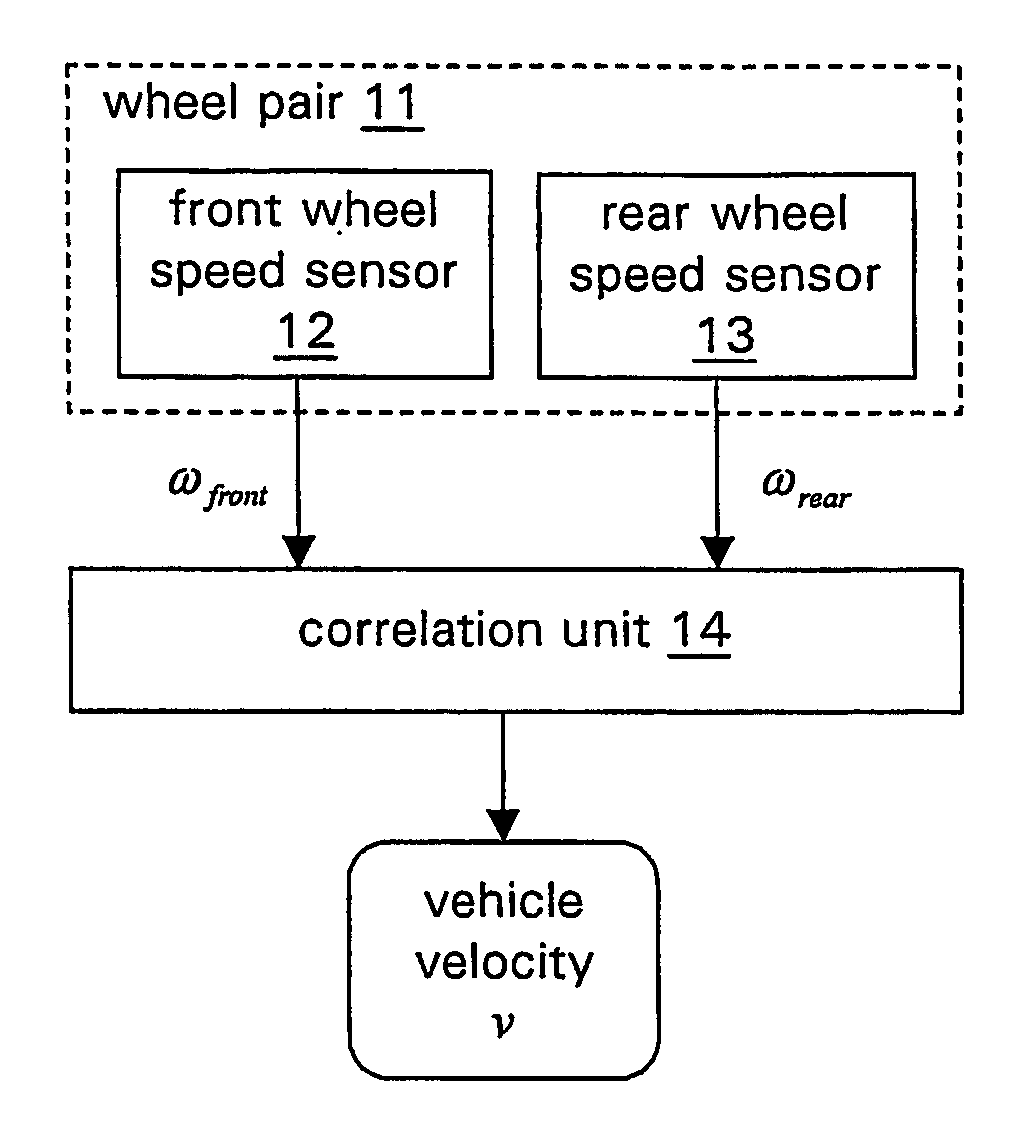
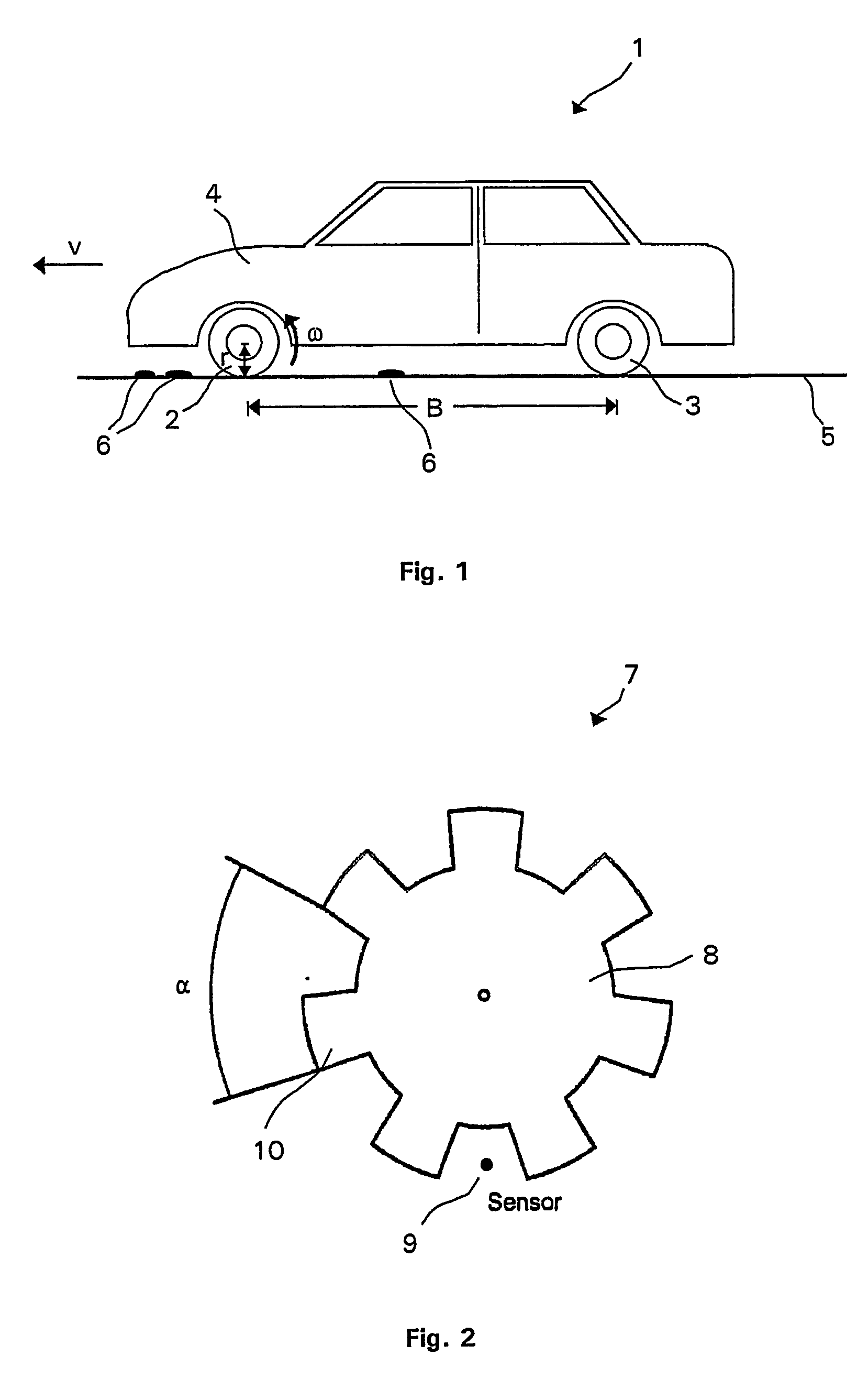
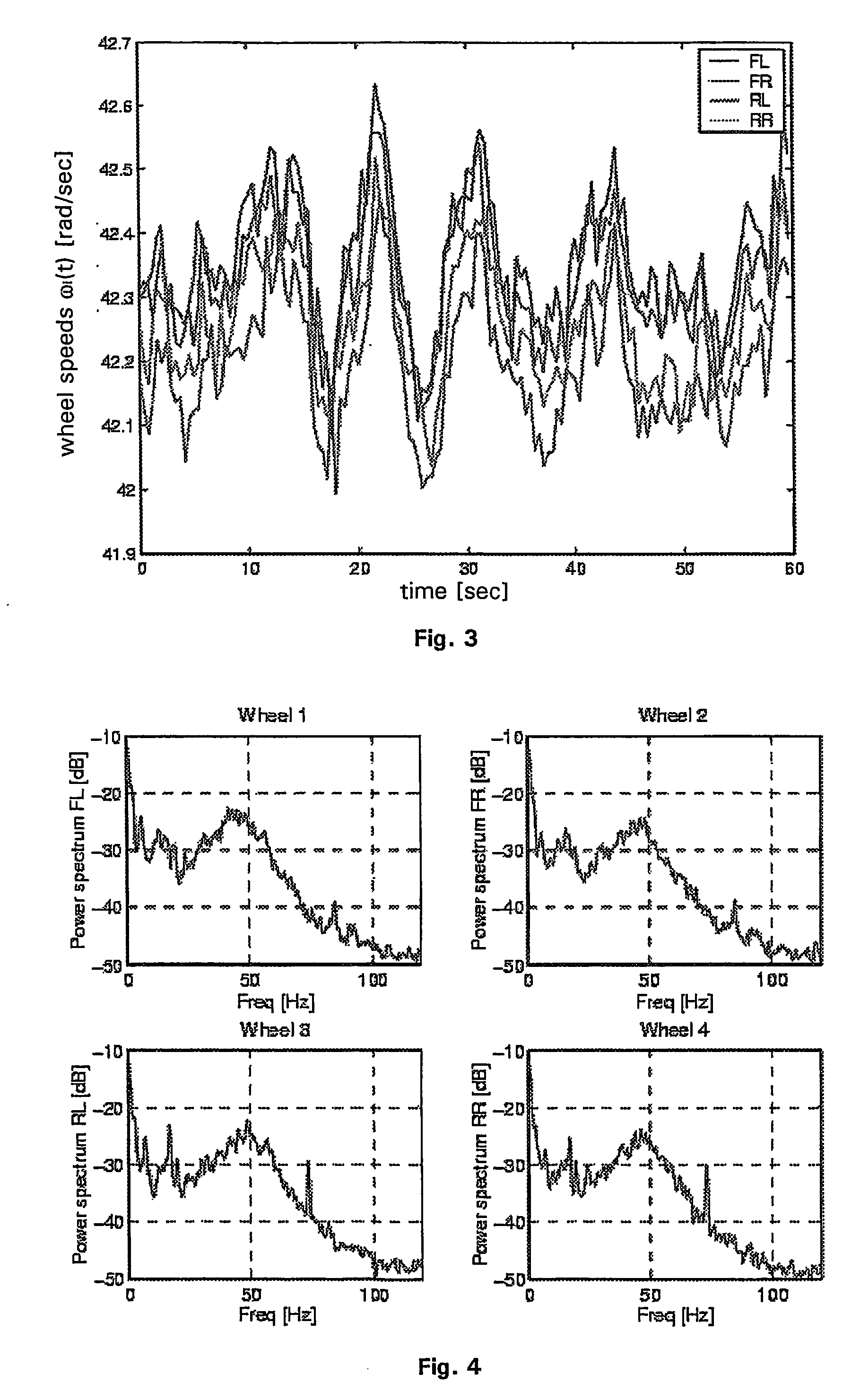
[0036] In general the presented method and system for determining the velocity of a vehicle is based on a correlation analysis of the time dependent behavior of wheel speed signals of a vehicle's front and rear wheels which varies with road bumpiness or unevenness. The cause for such variations may be any small or large road feature like asphalt texture, split, small stones, bumps, etc. These features induce these variations via the tire-road contact. The variations which are induced at a particular wheel result in a specific time dependent behavior of the respective wheel speed signal. The wheel speed signals are measured in a pair of a front and a rear wheel which are running in a lane so that they feel the same road features in a time delayed manner. Wheel speed sensors measure the front and rear wheel speed signals. The instantaneous wheel speed signals are influenced by the road features which were instantaneously passed by an individual wheel. A correlation analysis of the fro...


PUM


Abstract

A method of determining the velocity (ν) of a vehicle is provided. The vehicle has at least one pair of a front and a rear wheel which are spaced by a wheel spacing (B). Front and rear wheel speed signals (ω) are determined which are indicative of the time dependent behavior of the front and rear wheel speeds, respectively. The front and rear wheel speed signals (ω) are correlated in order to determine a specific correlation feature indicative of the time delay (τ) between the front wheel and rear wheel speed signals. The velocity (ν) of the vehicle is determined based on said correlation feature and the wheel spacing (B).

Description

FIELD OF THE INVENTION [0001] The present invention relates generally to a method of, a system for and a computer program product for determining the velocity of a wheeled vehicle. BACKGROUND OF THE INVENTION [0002] Knowledge of a vehicle's speed is fundamental to the driver, but also for many modern control systems as anti-lock braking systems (ABS), dynamic stability systems, anti-spin systems and traction control systems. Also, recent approaches to driver safety information systems, as road friction indicators and sensor-free tire pressure monitoring systems require precise velocity information. [0003] There are no standard sensors in commercial cars that can measure absolute velocity. The speedometer of wheeled vehicles is based on the formula ν=ωnom [m / s], where ω is the wheel rotational speed and rnom is the nominal wheel radius. The rotational speed of a wheel is accurately measured by on-board sensors, as available for example in the antilock braking system (ABS). Wheel radi...

Claims


Application Information

Patent Timeline
Patent Type & Authority Applications(United States)
IPC IPC(8): G06F15/00B60C23/06B60T8/172G01P3/48G01P3/66G01P3/80
CPCB60C23/061B60T8/172G01P3/803G01P3/48G01P3/66B60T2250/04
Inventor GUSTAVSSON, FREDRIK
Owner NIRA DYNAMICS AB
Learn More