
Method and apparatus for preparing signals to be compared to establish predistortion at the input of an amplifier

a technology of amplifier input and comparison signal, applied in the field of signal processing, can solve the problems of ineffective correction by applying a single fixed time shift to the comparison signal (reference signal) from the input side of the amplifier system, and the existing predistortion techniques do not address this problem, so as to improve radio performance and electrical efficiency of the radio amplifier. , the effect of improving the predistortion performan

Inactive Publication Date: 2003-08-21
EVOLIUM
View PDF3 Cites 120 Cited by
  • Summary
  • Abstract
  • Description
  • Claims
  • Application Information

AI Technical Summary

Benefits of technology

[0029] Given the above problems, an object of the invention is to provide a technique for time alignment of signals having a common origin and which, in one application, can dynamically calibrate and improve predistortion performance, implemented in digital form, in order to improve radio performance and the electrical efficiency of the radio amplifier.

Problems solved by technology

Existing predistortion techniques do not address this problem of error associated with the time-delay between the signals compared.
Note further that the time-delay is not fixed, and can vary with aging of the system, its temperature, the amplified signal, the power, the frequency band used, etc., which makes correction by applying a single fixed time shift to the comparison signal (reference signal) from the input side of the amplifier system somewhat ineffective.
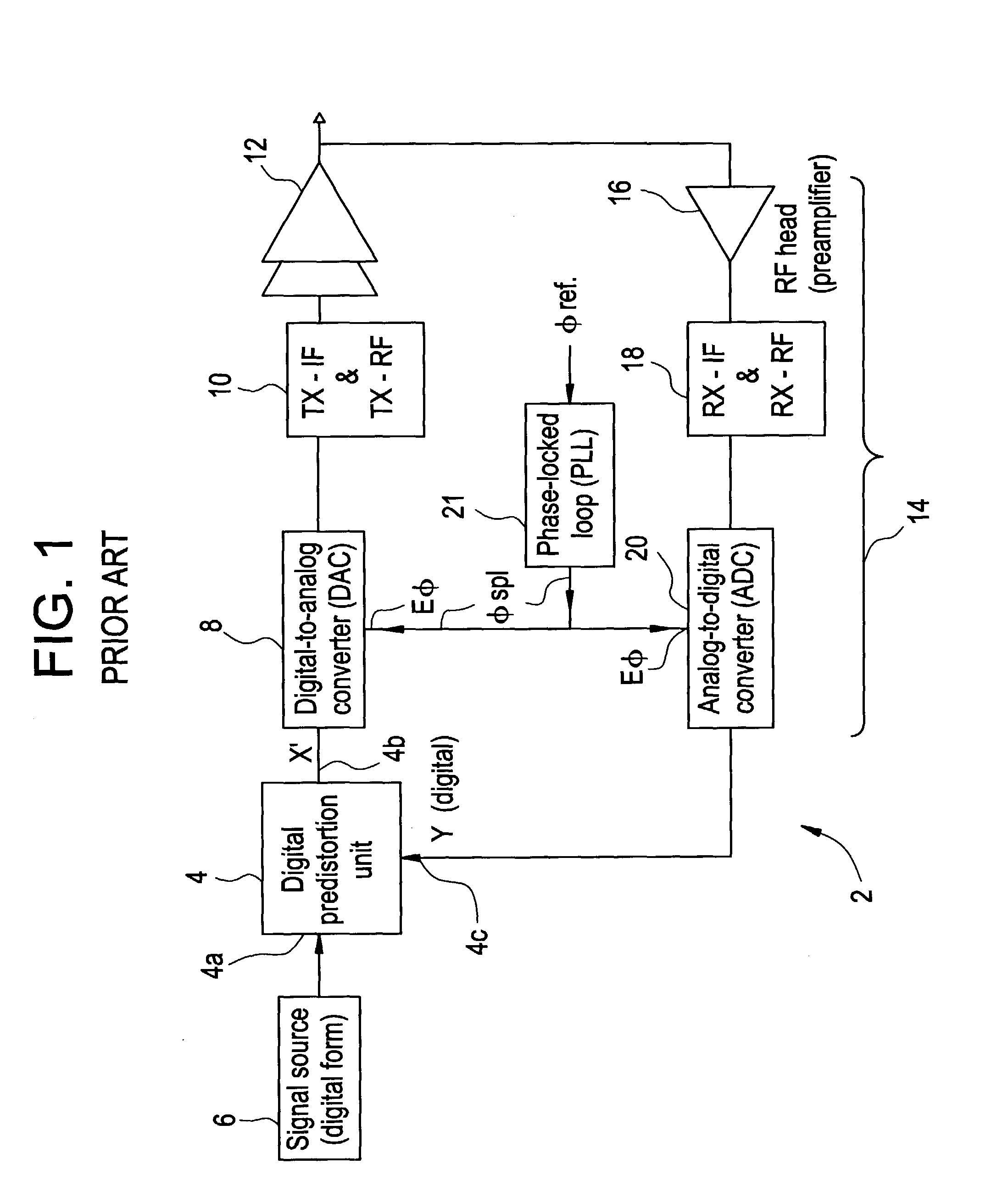
This results in limitations on performance caused both by the intrinsic calibration in the factory of phase alignment and most importantly of sampling time alignment between sending (sampling in the DAC 8) and receiving (sampling in the ADC 20), and also by inherent propagation times in the system, which are non-negligible and liable to vary, in particular because of the presence of analog filters.
Although the time shifts for the digital signals can be controlled, the problem is much more difficult in the analog domain.
This defective time alignment is particularly prejudicial to obtaining good predistortion performance at reasonable cost in modern transmitter stations, such as those used in third generation cellular systems.
The error in the predistortion calculated by this time shift could be corrected using algorithms, but this would require expensive calculation resources and would be based on approximations and extrapolations that would impose a fundamental limitation on accuracy.
This represents a significant advance over conventional amplification techniques known as "feedforward" techniques, the efficiency of which is limited to around 8%.
Most of these methods, based on least mean squares (LMS) algorithms, are relatively insensitive to the quadrature and the gain of the signals to be compared.
However, the major problem is the accuracy of the time-delays between the signals compared.
In fact, the problem is in all regards identical to that of wideband time-delay locking for a "feedforward" amplifier, except that it occurs in the digital domain in the case of predistortion.
In this case, the difficulty of the problem increases as the width of the band to be linearized increases.
Because of even greater variations in clock phase drift and variations throughout the transmit and receive system, this accuracy cannot be obtained by calibration in the factory.
The problem to be solved is that of finding methods for tracking and measuring time alignment dynamically and for correcting it using simple means that are preferably based on low-cost digital techniques.
This approach is very costly in terms of multipliers (for example Farrow filters, as described in the patent document WO 99 / 57806), because it operates at the sampling rate.

Method used


Image

  • Method and apparatus for preparing signals to be compared to establish predistortion at the input of an amplifier
  • Method and apparatus for preparing signals to be compared to establish predistortion at the input of an amplifier
  • Method and apparatus for preparing signals to be compared to establish predistortion at the input of an amplifier

Examples


Embodiment Construction

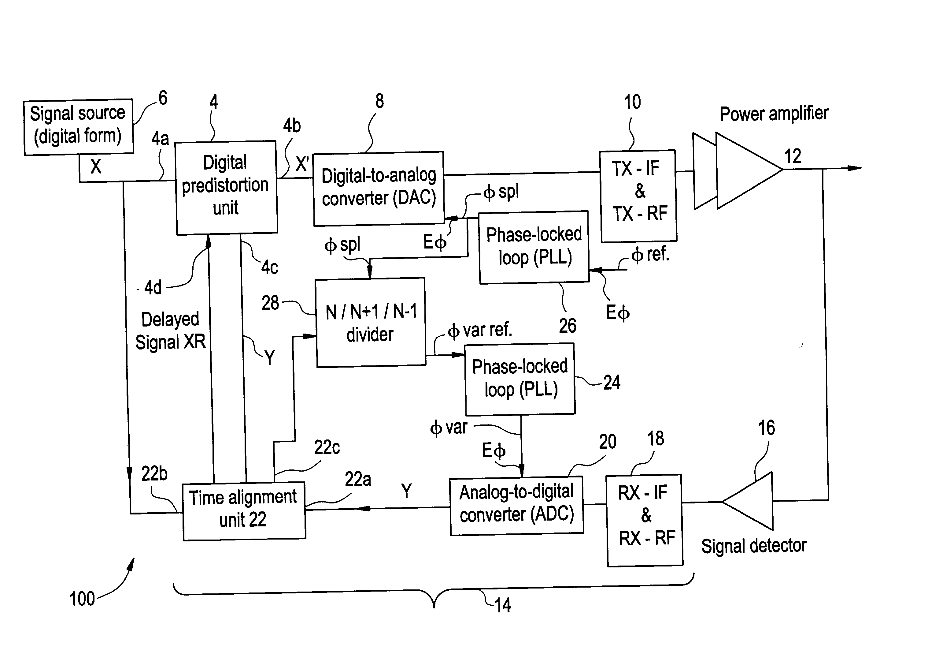
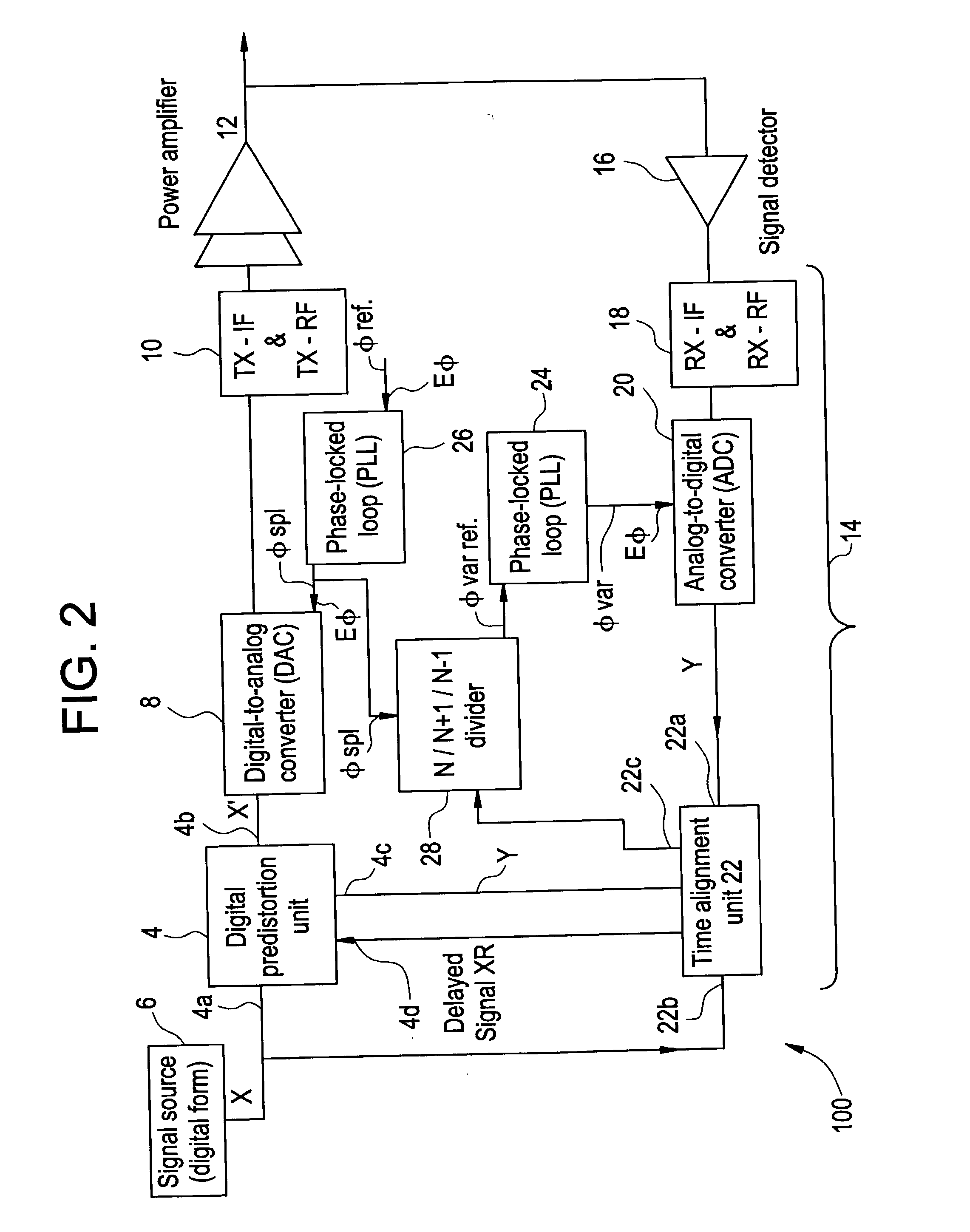
[0062] FIG. 2 shows an embodiment of the invention in the context of an amplifier system employing predistortion. In this figure, for conciseness, items analogous to those of FIG. 1 carry the same reference numbers and are not described again.

[0063] In this example, the digital signal source 6 of the system 100 produces a composite signal made up of a plurality of codes and frequencies, for example conforming to the 3GTP UMTS standard. In this case, a carrier consists of superposed orthogonal codes each carrying the information for one user. In modern techniques, it is desirable for there to be only one transmission system 100, and thus one amplifier system, for a given antenna sector or station. This implies that the same amplifier system be used not only for all the users on the same carrier but also for more than one carrier on the common radio site. One of the problems raised by this approach stems from the fact that each carrier is a signal that does not have a constant envelop...


PUM


Abstract

The invention relates to a method of preparing signals (X and Y) to be compared to establish predistortion at the input of an amplifier (12), the signals comprising a signal (X) before amplification and a signal (Y) after amplification by said amplifier. Preparation includes time aligning (22) the signal before amplification (X) with the signal after amplification (Y) before using them to establish said predistortion. The invention preferably operates in two stages, namely a stage of coarse time alignment, in which the signal before amplification (X) is subjected to a time delay comprising an integer number of first time units, and a stage of fine time alignment, in which a delay or advance value of a fraction of the first time unit is determined.

Description

[0001] The field of the invention is that of signal processing, more specifically in the context of correcting distortion produced by an amplifier system. Correction involves comparing the characteristics of the output signal with the original signal at the input of the amplifier system in order to determine the distortion that the system produces. This makes it possible to respond by calculating inverse predistortion to be applied to the input signal to cancel the distortion and thereby improve the linearity and the electrical efficiency of the amplifier system.[0002] The invention is based on the observation that, because the amplifier system introduces a time-delay, the comparison is not applied to the signal and to its exact replica (ignoring the intrinsic distortion of the system), and that this leads to non-negligible error and puts a theoretical limit on how well predistortion can be calculated.[0003] Existing predistortion techniques do not address this problem of error asso...

Claims


Application Information

Patent Timeline
IPC IPC(8): H03F1/32
CPCH03F1/3294H03F1/3247
Inventor DARTOIS, LUC
Owner EVOLIUM
Learn More