
Multifunctional fluorescence diagnosis system

a fluorescence diagnosis and multi-functional technology, applied in the field of fluorescence diagnosis system, can solve the problem of not being able to present certain tissue functional properties, and achieve the effect of good contrast and high contras

Active Publication Date: 2006-10-26
KARL STORZ GMBH & CO KG
View PDF35 Cites 81 Cited by
  • Summary
  • Abstract
  • Description
  • Claims
  • Application Information

AI Technical Summary

Benefits of technology

[0019] The use of excitation light in the NIR range has the advantage that it is absorbed only weakly by human tissue, with the result that deeper-lying blood vessels can also be viewed. In addition, the excitation frequency range in the NIR range differs greatly from that of the most commonly used tumor marker 5-ALA, whose excitation frequency range lies in the blue wavelength range.
[0051] If the fluorescence diagnosis system now has a sensor for recording an ECG signal, this signal can be used to trigger the storage of image data. This technique is also referred to as ECG triggering. By this means, the image data are recorded in phase synchronization, that is to say the image data are always recorded at the same point during a heart beat, for example in synchronization with the QRS complex or the R wave. In this way, such artefacts can be avoided.

Problems solved by technology

However, it is not possible to present certain functional properties of the tissue with this system.

Method used


Image

  • Multifunctional fluorescence diagnosis system
  • Multifunctional fluorescence diagnosis system
  • Multifunctional fluorescence diagnosis system

Examples


Embodiment Construction

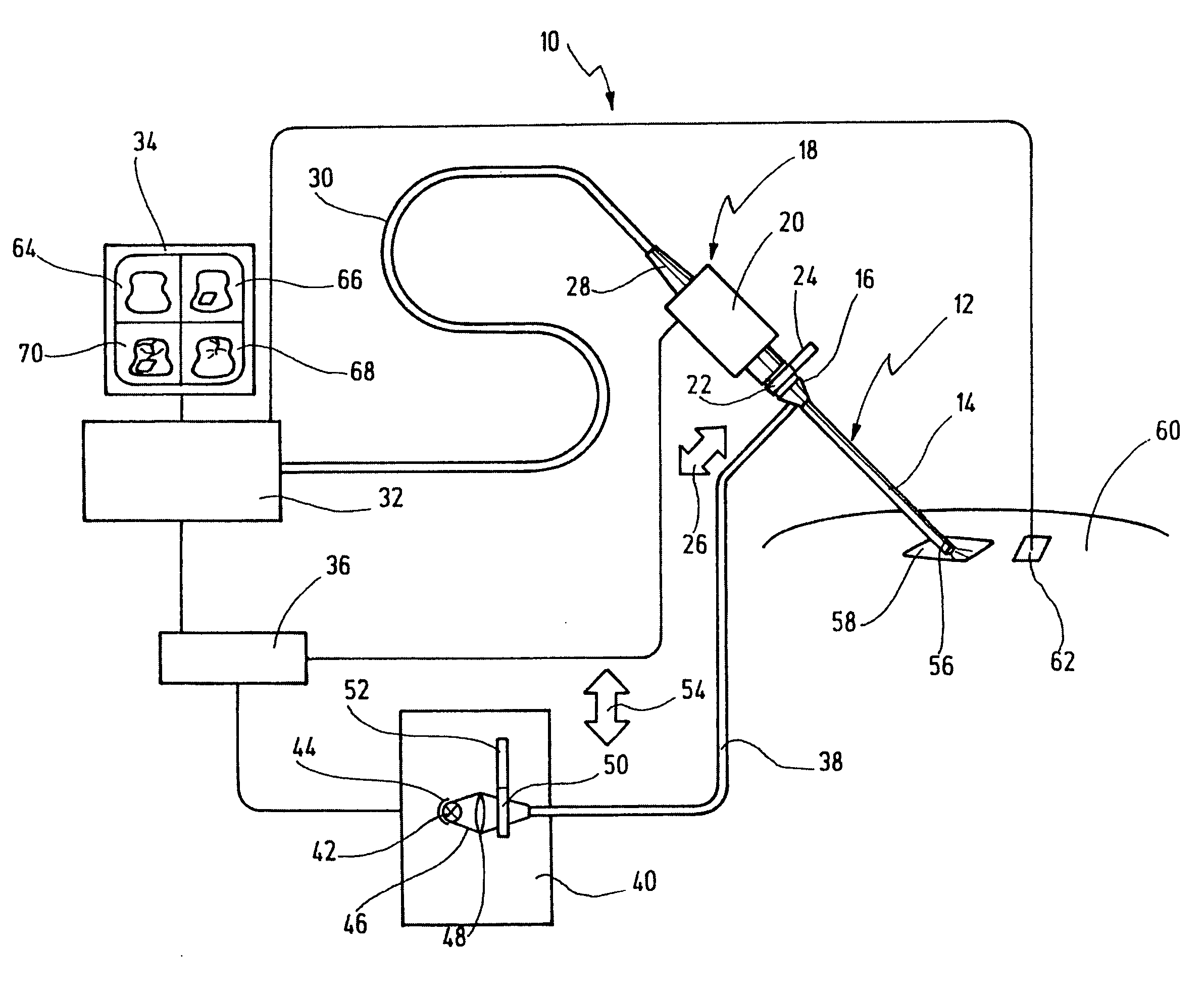
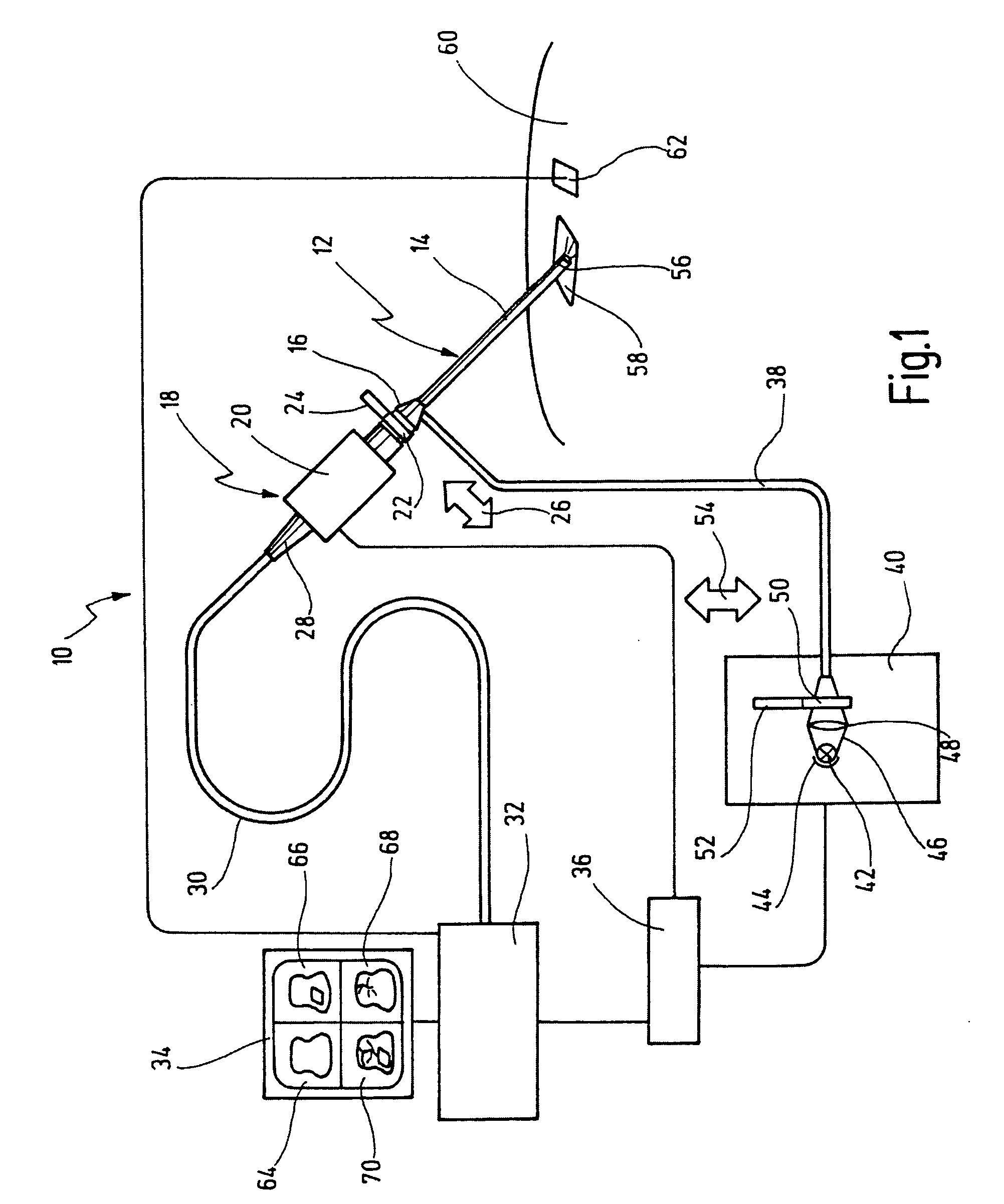
[0054] In FIG. 1, a fluorescence diagnosis system is designated in its entirety by reference number 10.

[0055] The fluorescence diagnosis system 10 comprises a viewing system 12, which is here designed as an endoscope 14. The design of the viewing system 12 as an endoscope 14 is preferred, since tissue inside a patient's body can in this way be examined while causing the patient minimal stress. However, other viewing systems are also conceivable, for example microscopes. At a proximal end 16, the endoscope 14 has a camera system 18, which is here designed as a video camera 20. The camera system 18 and the endoscopes 14 can also be designed in one unit, for example in the form of a video endoscope. A filter 22 is also arranged between the video camera 20 and the proximal end 16 of the endoscope 14.

[0056] The filter 22 is connected to a further filter 24 and can be moved, in the direction of a double arrow 26, between the video camera 20 and the proximal end 16 of the endoscope 14. B...


PUM


Abstract

A fluorescence diagnosis system has a viewing system at least one light source and a camera system. The at least one light source can be operated in three modes, a first generating white light, a second with a first fluorescence excitation light of a first excitation wavelength and a third in which a second fluorescence excitation light of a second excitation wavelength is generated producing a fluorescence image in the NIR range. The camera system is sensitive at least in the visible and the NIR range. The system further comprises an image processing system for converting the fluorescence image in the NIR range into a visible image.

Description

CROSS-REFERENCE TO RELATED APPLICATIONS [0001] This application claims priority of German patent application No. DE 20 2005 003 411.8 filed on Dec. 24, 2005. BACKGROUND OF THE INVENTION [0002] The present invention relates to a fluorescence diagnosis system. [0003] Such a fluorescence diagnosis system is used, for example, for what is called photodynamic diagnosis of tumors. In photodynamic diagnosis, a patient is administered a suitable tumor marker substance, for example 5-aminolevulinic acid (5-ALA). 5-ALA is a precursor in heme biosynthesis. 5-ALA collects in tumor tissue and causes a fluorescence that can be excited with a specific wavelength. Areas in which 5-ALA has collected, that is to say tumorous areas, fluoresce in a red color. Since blue light is used as the excitation light, this can be filtered out in the observed view, and the tumorous areas thus stand out clearly from the healthy tissue. [0004] It is also known that healthy tissue fluoresces at certain wavelengths o...

Claims


Application Information

Patent Timeline
IPC IPC(8): A61B6/00
CPCA61B1/00009A61B1/043A61B1/0638A61B1/307A61B5/0071A61B1/0646A61B5/413A61B5/721G01N21/6428G01N21/6456A61B1/00186A61B5/0084
Inventor IRION, KLAUS M.EHRHARDT, ANDREBAUMGARTNER, REINHOLDSTEPP, HERBERTPONGRATZ, THOMAS
Owner KARL STORZ GMBH & CO KG
Learn More