
Excimer laser device, laser gas exchange method and partial gas exchange quantity calculation method

a laser device and laser gas exchange technology, applied in the direction of laser details, active medium materials, electrical devices, etc., can solve the problems of reducing production throughput, achieve the effect of reducing the frequency of full gas exchange, reducing and improving the production throughput of semiconductor lithography

Active Publication Date: 2006-10-26
GIGAPHOTON +1
View PDF8 Cites 32 Cited by
  • Summary
  • Abstract
  • Description
  • Claims
  • Application Information

AI Technical Summary

Benefits of technology

The present invention provides an excimer laser device and method that reduces the frequency of full gas exchange in the laser chamber and more preferably eliminates the need for full gas exchange. This is achieved by controlling the gas supply and exhaust devices to carry out partial gas exchange in a gas exchange quantity that maintains the impurities in the laser chamber at a constant level. This results in improved production throughput in semiconductor lithography and other processes that use the excimer laser device. Additionally, the invention provides a method for calculating the optimal partial gas exchange quantity based on the output light energy reduction, gas pressure, and output light energy reduction per unit time.

Problems solved by technology

To fully exchange the laser gas, laser operation is stopped, so for example the semiconductor lithography process is stopped, which has the problem that production throughput is reduced.

Method used


Image

  • Excimer laser device, laser gas exchange method and partial gas exchange quantity calculation method
  • Excimer laser device, laser gas exchange method and partial gas exchange quantity calculation method
  • Excimer laser device, laser gas exchange method and partial gas exchange quantity calculation method

Examples


Embodiment Construction

[0036] The following is a detailed description of the preferred embodiments of the present invention, with reference to the drawings.

[0037] The amount of increase in impurities in the laser chamber can be estimated to be virtually proportional to the reduction in output light energy. The present application is based on this assumption. Therefore, firstly the results of a quantitative study of how in conventional partial gas exchange impurities vary within the laser chamber, or in other words how output light energy reduces, will be explained.

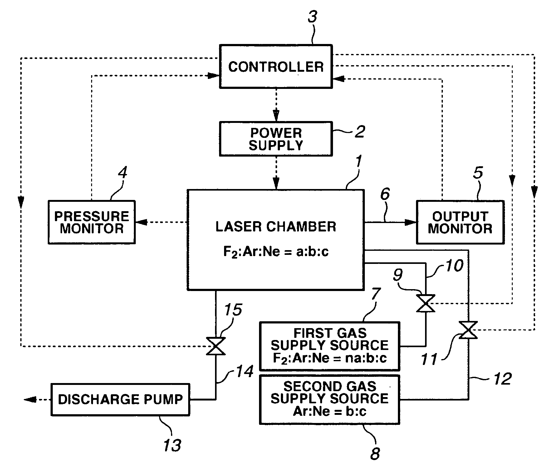
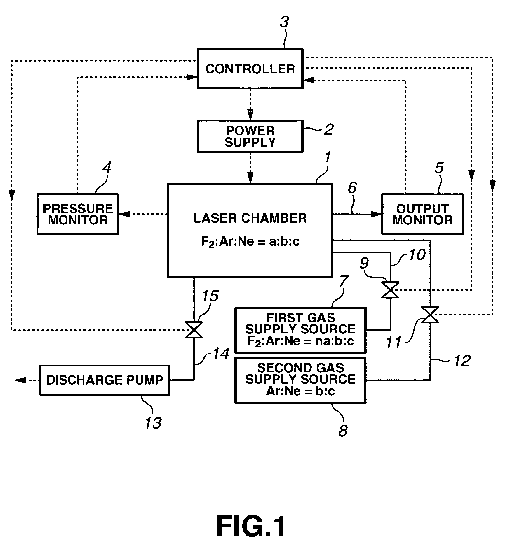
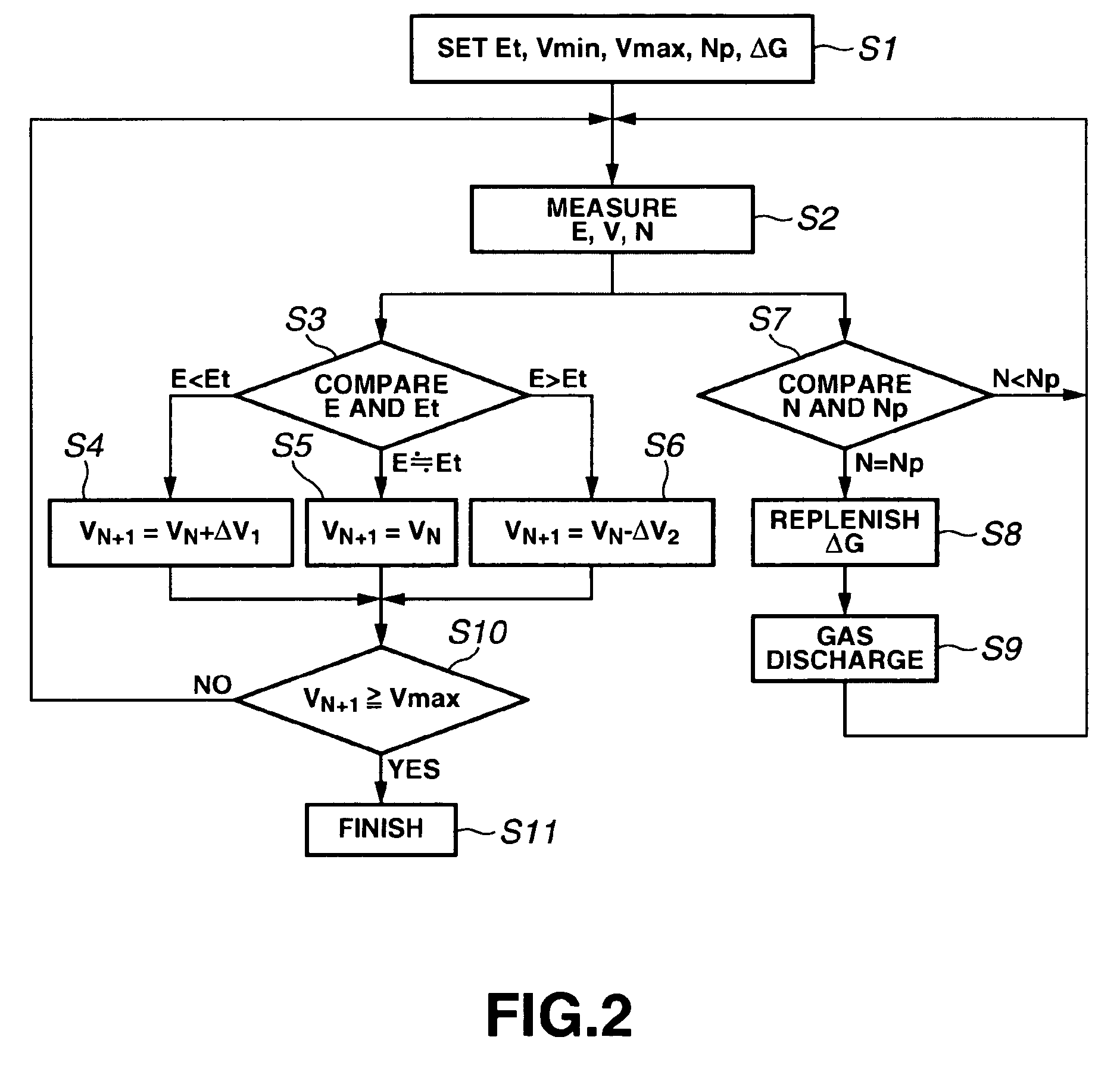
[0038] The gas control device used in the present application is the conventional device shown in FIG. 1. Also, the partial gas exchange control flow is basically the same as the conventional method shown in FIG. 2. The part that differs from the conventional method is the gas exchange amount ΔG in the gas replenishment carried out in Step S8 of FIG. 2.

[0039] The following is a detailed explanation of the partial gas exchange amount ΔG.

[0040...


PUM


Abstract

To provide an excimer laser device and method in which the frequency of full gas exchange within the laser chamber is reduced, and more preferably full gas exchange is made unnecessary. The gas supply device and gas exhaust device are controlled so that the laser gas in the laser chamber is partially exchanged in a gas exchange quantity that maintains the quantity of impurities in the laser chamber at or below a fixed level. Also, the gas exchange quantity is obtained using the total quantity of output light energy reduction A, the total gas pressure in the laser chamber P, and output light energy reduction quantity per unit time k, for the case where partial gas exchange is repeated infinitely in the laser chamber.

Description

BACKGROUND OF THE INVENTION [0001] 1. Field of the Invention [0002] The present invention relates to an excimer laser device and method in which the frequency of full gas exchange within the laser chamber is reduced, and more preferably full gas exchange is made unnecessary. [0003] 2. Description of the Related Art Deterioration of Laser Gas and Countermeasures Against It [0004] In excimer laser devices, a mixture of halogen gas, noble gas, and buffer gas is enclosed within the laser chamber for generating laser oscillations. As the excimer laser device is operated, the halogen gas enclosed in the laser chamber is consumed, and the reduction in halogen gas causes the output light energy of the excimer laser to reduce. In the following, explanations are provided as examples for a KrF excimer laser and an ArF excimer laser, which use fluorine gas as the halogen gas. [0005] The main reason for the reduction in fluorine gas is parts within the laser chamber in contact with the fluorine...

Claims


Application Information

Patent Timeline
Patent Type & Authority Applications(United States)
IPC IPC(8): H01S3/223H01S3/22
CPCH01S3/036H01S3/225H01S3/134
Inventor MATSUNAGA, TAKASHIABE, TORU
Owner GIGAPHOTON
Learn More