
Dishwasher drying system

Inactive Publication Date: 2006-10-26
VIKING RANGE
View PDF13 Cites 103 Cited by
  • Summary
  • Abstract
  • Description
  • Claims
  • Application Information

AI Technical Summary

Benefits of technology

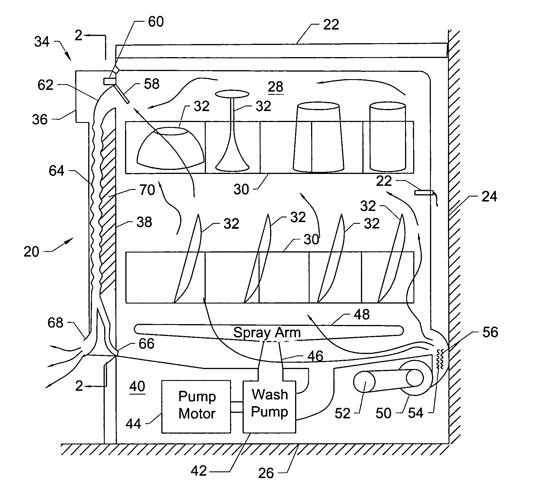
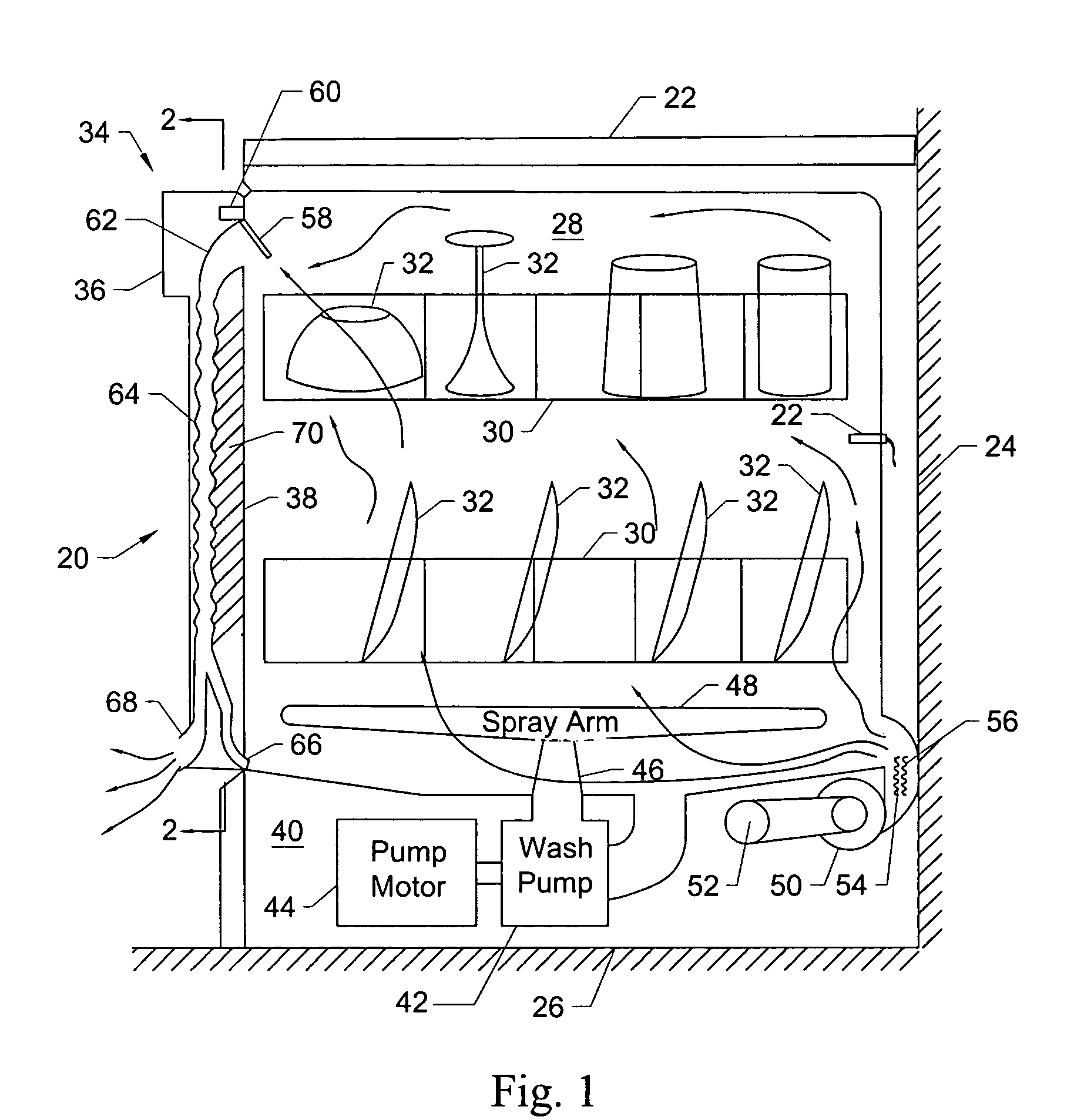
[0005] The present invention improves conventional drying cycle techniques by utilizing a forced convection design, a moisture laden air condensation element, and a control system to terminate drying as soon as the dishes are determined to have reached their dry state. The present drying system uses a relatively small forced convection blower to force air from the enclosure underneath the machine into the lower portion of the dishwasher tub or washing chamber. Since the inlet is disposed in the lower rear of the dishwasher, the present drying cycle uses the heat transferred from the bottom of the tub of the dishwasher and generated by the pump motor during the wash cycle. Additionally, an electric air heating element is located adjacent the blower to heat the inlet air before it is forced into the dishwasher tub and mixed with the turbulent air in the tub. The turbulent airflow also promotes an even temperature distribution over the dish load throughout the dishwasher. If the air heater were positioned out of the air stream, the heating of the dishes would be less uniform. Although the uniform temperature distribution is important for uniform drying, the uniformity also allows a temperature reading to be taken at one location inside the dishwasher to accurately represent the temperature throughout the dishwasher interior. This temperature information can then be used to detect when the majority of the water has been vaporized from the surface of the dishes.
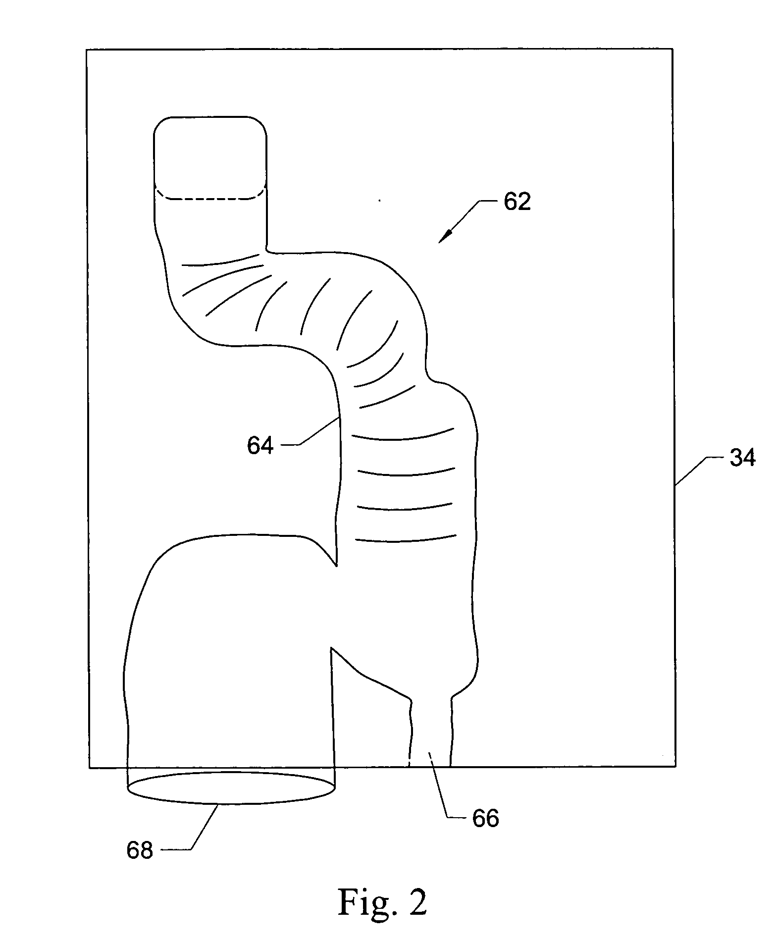
[0006] The exhaust vent assembly is located in the door of the present dishwasher. In order to reduce the temperature and moisture content of the air being expelled into the area around the dishwasher, the exhaust vent is shaped it to act as a condenser. The condenser portion of the exhaust vent assembly has convolutions or corrugations, which increase the surface area available for condensation for the water vapor inside the condenser. The condenser section is separate from, and thermally insulated from, the interior of the dishwasher to prevent the inside of the dishwasher from heating the surfaces of the condenser. Minimal insulation is included between the condenser and the outside of the dishwasher to allow the condenser surface that transfers heat to the area around the dishwasher to remain relatively cool and to increase the efficiency of the condenser. The water that condenses in the vent is directed back to the sump of the dishwasher and the exhaust air is vented into the room or area around the dishwasher from the bottom of the door. This exhaust air enters the room at a relatively low velocity because the area of the vent is relatively large. In addition, the moisture content and temperature of the air being exhausted into the room is reduced, which alleviates the conventional problems caused by heat and the formation of water droplets.

Problems solved by technology

If the air heater were positioned out of the air stream, the heating of the dishes would be less uniform.
As the drying cycle progresses, the heat contained by the dishes from the final rinse quickly dissipates.
When all of the water has vaporized from the surface of the dishes, the rate of decrease of the temperature of the air being exhausted will slow.

Method used


Image

  • Dishwasher drying system
  • Dishwasher drying system
  • Dishwasher drying system

Examples


Embodiment Construction

[0011]FIG. 1 illustrates a dishwasher 20 installed under a counter 22 against a back wall 24 on a floor 26. The dishwasher 20 includes tub portion 28 defining an interior cavity holding racks 30, which carry articles 32 to be washed. The dishwasher 20 includes a door 34 of double wall construction having a front wall 36 facing the exterior and an interior wall 38 facing into the tub 28 of the dishwasher 20. Typically, the controls for the dishwasher 20 are incorporated into the door 34. For the sake of simplicity in this illustration, the controls have been omitted from FIG. 1. Positioned below the tub 28 is a lower cavity 40 that contains several operational components of the dishwasher, such as a wash pump 42 and a wash pump motor 44. The wash pump 42 and wash pump motor 44 are isolated from the tub 28 and are not exposed to wash water therein. The wash pump 42 supplies water for washing the articles 32 through a hollow shaft 46, which, in turn, supplies water to a spray arm 48, p...


PUM


Abstract

A dishwasher with a novel drying cycle is provided. The dishwasher door includes a vent channel connecting the interior of the dishwasher to the outside and housing a condenser section that condenses water vapor from moisture laden air from the interior of the dishwasher and directs the condensed water back into the dishwasher. A vent valve covers the opening of the vent channel into the dishwasher and is opened and closed at appropriate times during the drying cycle. A heater adjacent a blower heats air entering the dishwasher. A temperature sensor in the dishwasher interior provides temperature measurements of the inside of the dishwasher that may be used to control the duration of the drying cycle. A controller interconnects the operating components of the dishwasher and provides the logic for the drying cycle.

Description

FIELD OF THE INVENTION [0001] The present invention relates to a dishwasher that incorporates a novel drying system. BACKGROUND OF THE INVENTION [0002] Most domestic dishwashers incorporate a drying cycle as the last phase of an overall dishwashing cycle. One way to operate a drying cycle in a dishwasher is to allow the final rinse temperature in the dishwasher to reach a relatively high temperature to ensure that the dishes are relatively hot and contain a relatively large amount of thermal energy at the end of the final rinse. Drying is accomplished by a combination of water dripping from the dishes and water vaporizing directly from the dishes' surface. The rate at which the water drips from the dishes slows quickly and vaporization becomes the dominant mechanism of drying. In the early part of the drying phase, the thermal energy contained by the dishes from the final rinse of water supplies most of the energy to drive the water vaporization process. Once the air inside the dish...

Claims


Application Information

Patent Timeline
IPC IPC(8): F26B21/06F26B3/00
CPCA47L15/0034A47L15/4257A47L15/483A47L15/488A47L2501/30A47L2501/10A47L2501/11A47L2501/12A47L15/0047A47L2401/18
Inventor FERGUSON, JERRY WAYNEMORRISON, JOHN FREDERICKRYALS, JEFFREY ALANWEAVER, DAVID CLINTON
Owner VIKING RANGE
Learn More