
Stent supplying device

a technology of supplying device and stent, which is applied in the field of stent delivery system, can solve the problems of not being able to implant stent in the targeted area, not being able to establish a treatment method, and affecting the blood vessel

Inactive Publication Date: 2006-10-19
IGAKI IRYO SEKKEI
View PDF43 Cites 78 Cited by
  • Summary
  • Abstract
  • Description
  • Claims
  • Application Information

AI Technical Summary

Benefits of technology

[0025] It is an object of the present invention to provide a stent delivery system whereby a stent for a vessel, formed of a biodegradable polymer and afforded with the self-expanding properties, may correctly be implanted in a target site in the vessel.
[0026] It is another object of the present invention to provide a stent delivery system whereby a stent for a vessel, which is formed of the biodegradable polymer and given the self-expanding properties, but which is furthermore in need of expansion by a balloon, may be enlarged in diameter such as to provide a reliable support for the inner wall of the vessel.
[0028] It is a further object of the present invention to provide a stent delivery system whereby a stent for a vessel, mounted on the balloon, provided to the catheter, may readily be delivered to a targeted site for implantation in the vessel.
[0029] It is yet another object of the present invention to provide a stent delivery system whereby a stent for a vessel may be delivered without falling off within a small vessel which may be bent, sinuous or hardened.
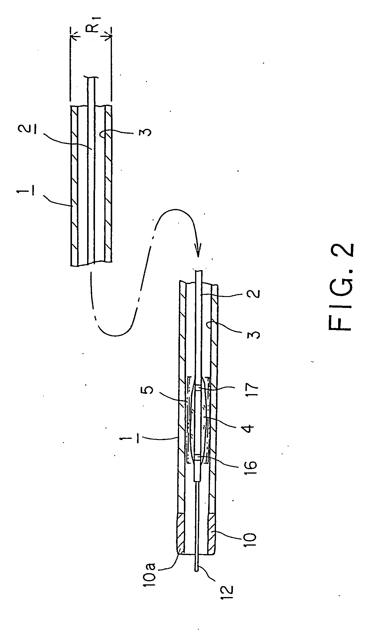
[0044] Since the radiopaque section containing a radiopaque material is provided on the distal end side of the protective sheath, and the catheter inserted into the protective sheath includes a radiopaque section indicating the mounting position of the stent for a vessel, the relative positions of the radiopaque section on the protective sheath side and the radiopaque section on the catheter may be confirmed, when the protective sheath is moved relative to the stent for a vessel, whereby it is possible to determine the positions of the catheter and the stent for a vessel relative to the protective sheath.

Problems solved by technology

Currently, there has not been established a method for treatment for an instance where re-stenosis has occurred on a site where angioplasty has been applied and a metal stent has been implanted.
Moreover, if metal, inherently a foreign substance for the living body, is caused to remain for a prolonged time in the living body, there is a cause that the blood vessel may thereby be affected, such as by excessive intimal hyperplasia occurring in the stent implant portion.
The result is that not only the stent cannot be implanted in the targeted site for implantation in the blood vessel but also the stent becomes unable to be expanded by the balloon.

Method used


Image

  • Stent supplying device
  • Stent supplying device
  • Stent supplying device

Examples


Embodiment Construction

[0064] Referring to the drawings, present embodiments of the present invention will be explained in detail.

[0065] The stent delivery system according to the present invention is used for delivering a stent, implanted in a vessel, such as blood vessel, trachea, bile duct or urethra of a living body, for supporting the lumen of the vessel from its inner side for maintaining a patency state of the lumen, to a target site for implantation in the vessel.

[0066] In the embodiment, as now explained, the present invention is applied to a system for delivery in the blood vessel of a stent for a vascular vessel to be implanted within the blood vessel of the living body.

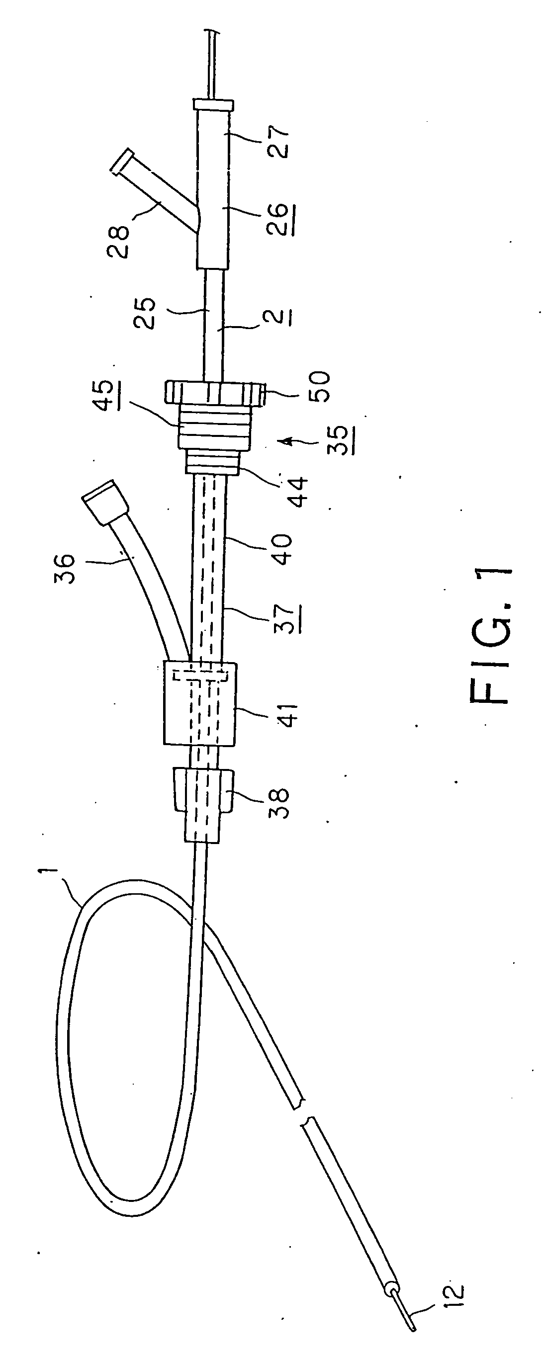
[0067] The stent delivery system, embodying the present invention, includes a protective sheath 1, inserted into the vessel, such as a blood vessel, of a living body, and a catheter 2, inserted into the protective sheath 1 and inserted along with the protective sheath 1 into the blood vessel, as shown in FIG. 1.

[0068] The pr...


PUM


Abstract

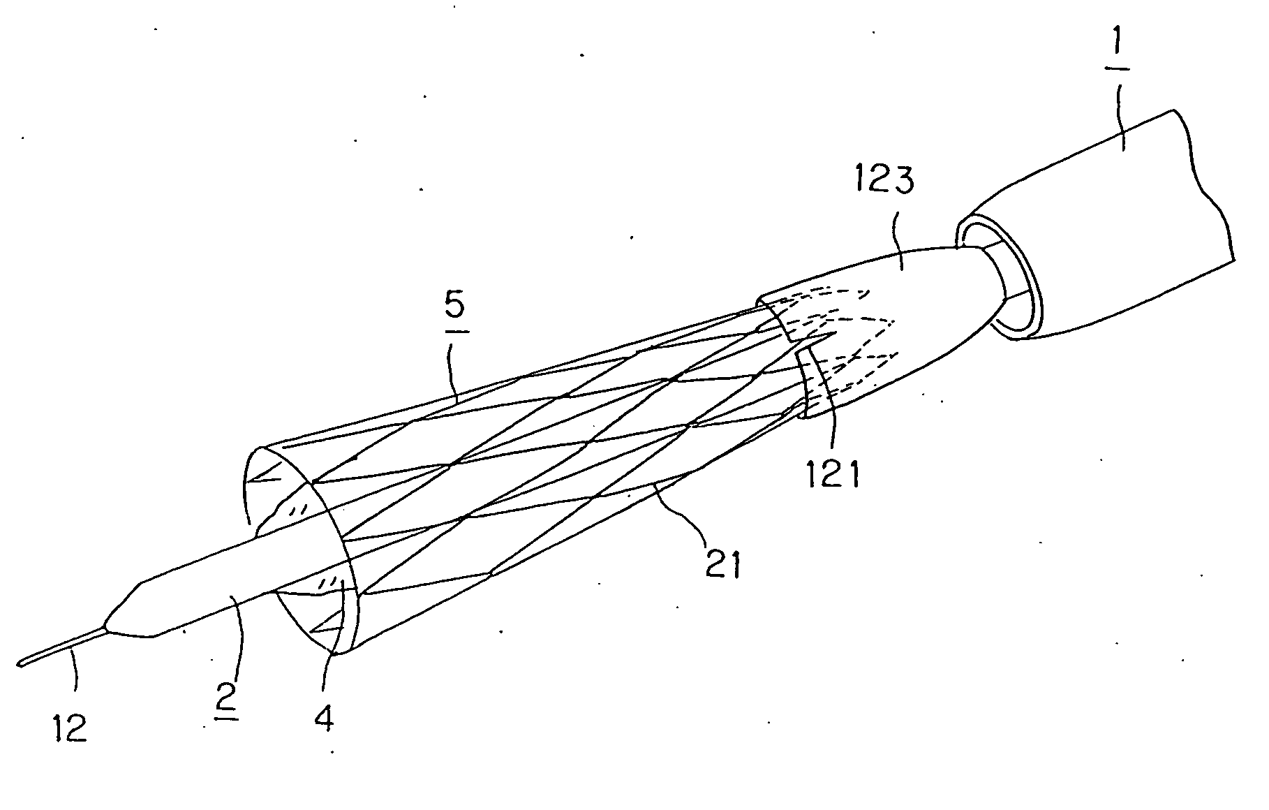
Disclosed is an apparatus for delivery of a stent for a vessel used for implanting the stent for a vessel in the blood vessel. The delivery system includes a protective sheath (1), inserted into the vessel of a living body, a catheter (2) inserted for back-and-forth movement in the protective sheath (1), a balloon (4) arranged on the outer peripheral surface towards the distal end side of the catheter (2), configured to be protruded from the distal end of the protective sheath (1), so that the balloon is expanded by a fluid supplied to the catheter (2), and a stent for a vessel (5) formed of a biodegradable material. The stent for a vessel (5) is mounted in a state contracted in diameter on the balloon (4) and is moved back and forth along with the balloon (4) relative to the protective sheath (1). The stent for a vessel has at least one end part temporarily held by a temporary holding member (23).

Description

TECHNICAL FIELD [0001] This invention relates to a stent delivery system used for delivering a stent for a vessel, implanted in a vessel of a living body, such as blood vessel, trachea, bile duct or urethra, for providing a support for the lumen of the vessel from the inside, to a target site for implantation in the vessel. [0002] This application claims priority based on the JP Patent Application 2003-146770, filed in Japan on May 23, 2003, which is incorporated by reference herein. BACKGROUND ART [0003] If stenosis has occurred in a vessel of a living body, such as blood vessel, a balloon forming portion provided in the vicinity of the distal end of a balloon catheter is inserted into this stenosis portion. This balloon forming portion is dilated to expand the stenosis portion of the blood vessel to improve the blood flow. This operation, known as percutaneous angioplasty (PTA), has so far been in widespread use. [0004] However, after application of PTA to the site of occurrence o...

Claims


Application Information

Patent Timeline
IPC IPC(8): A61F2/84A61F2/958A61F2/966A61M29/00A61M29/02
CPCA61F2/958A61F2/966A61F2002/9665A61F2002/9517A61F2/97A61F2/962A61F2/9517A61F2/07A61F2/95A61M25/10A61M29/00
Inventor IGAKI, KEIJI
Owner IGAKI IRYO SEKKEI
Learn More