
Vascular graft

a technology of vascular grafts and endovascular arteries, which is applied in the field of vascular and endovascular grafts, can solve the problems of affecting circulation, affecting circulation, and causing internal bleeding and eventual death in many cases, and affecting circulation

Inactive Publication Date: 2006-10-12
LIMERICK UNIV OF
View PDF11 Cites 63 Cited by
  • Summary
  • Abstract
  • Description
  • Claims
  • Application Information

AI Technical Summary

Benefits of technology

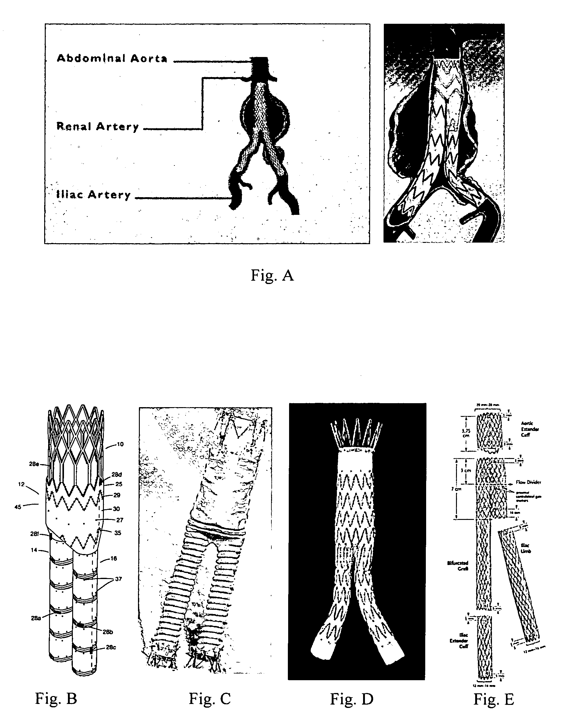
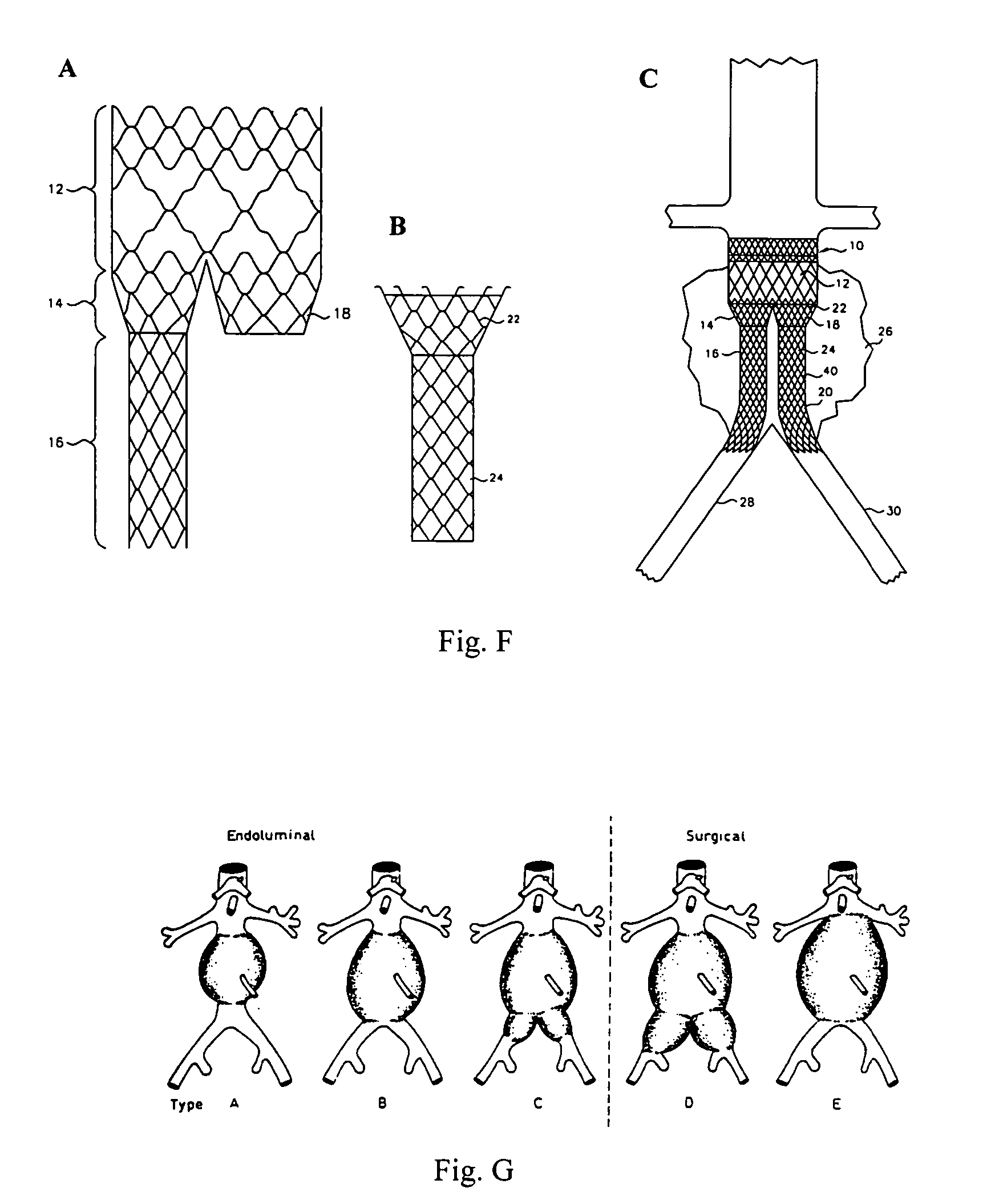
[0005] The graft itself is a synthetic material often supported with a metal (typically nitinol or 316L stainless steel) endoskeleton. Graft fixation is often achieved by the stent which creates a fixation at the proximal end by barbs or by a stent portion that is uncovered by graft material. Distal end fixation is attained by friction within the branch or iliac arteries. Such endovascular treatments offer the economic advantages of short hospital stays or even treatment as an outpatient, as well as elimination of the need for postoperative intensive care and are, therefore, extremely attractive to both patients and physicians.
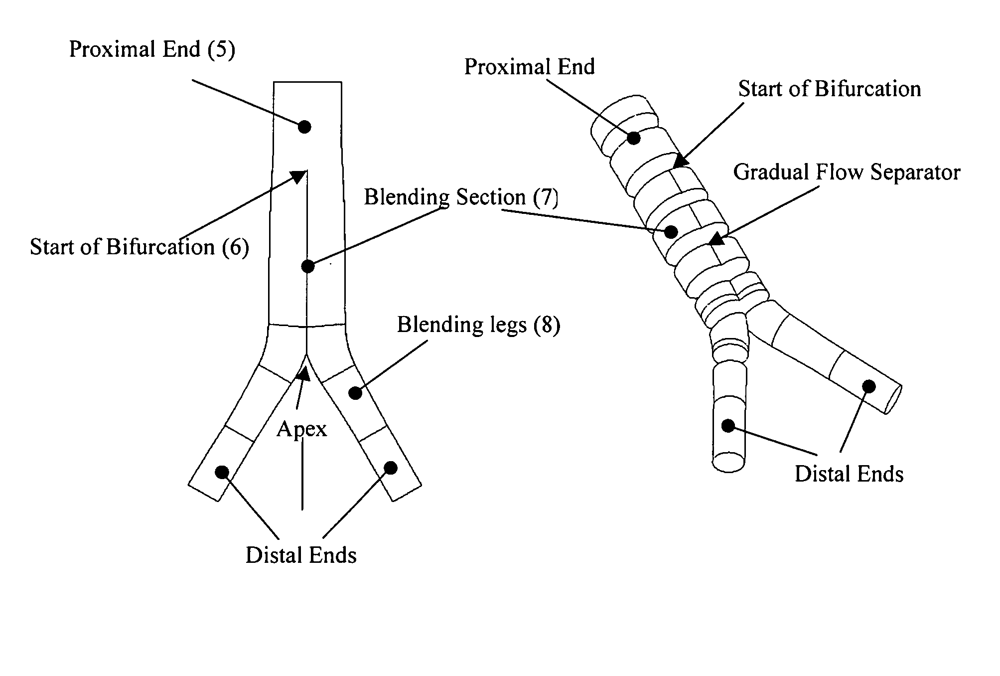
[0027] In one embodiment of the invention the blending section is shaped to minimise pressure wave reflection back to the proximal section. The blending section may be shaped to minimise flow recirculation. The blending section may be shaped to minimise skewing of flow and secondary flow profiles throughout the graft.
[0055] In another embodiment, the blending section provides for a small difference in cross-sectional area between the proximal section and the total cross-sectional area of the distal legs.

Problems solved by technology

Damage to the media gives rise to AAA.
Over time the vessel wall loses its elasticity and the normal blood pressure in the aneurysm sac can lead to rupture of the vessel wall, which causes internal bleeding and eventual death in many cases.
Even if the vessel wall does not rupture, a large aneurysm can impede circulation and promote unwanted blood-clot formation.
However, standard AAA repair is not perfect, and the quality of life after this repair is impaired by postoperative pain, sexual dysfunction, and a lengthy hospital stay resulting in high health costs.
These negative effects are related to the large incision and extensive tissue dissection.
The standard repair is also extremely difficult in patients with a prior history of abdominal operations where extensive scarring and infection may be present.
Long-term results are not so encouraging with stent graft migration, endoleaks, material failure and aneurysm rupture all being reported.
Problems due to stent graft fixation can lead to endoleaks and stent graft migration, leaving the aneurysm exposed to systemic blood pressure.
A well-known complication with this endovascular procedure is the late migration of the graft in which most of the devices are diagnosed after the first 12 months after the procedure.
The effect of the migration is to expose the aneurysm sac to systemic blood pressure and flow, which if left untreated has serious consequences for the patient.
This generates systemic pressurization of the aneurysm sac that eventually leads to expansion and rupture.
Endovascular stent graft fatigue failures have been recognized in devices after aortic implantation.
This fatigue failure leads to delayed hook fractures, metallic stent fractures, suture disruptions, fabric erosion (caused by abrasion of the polyester woven fabric with the underlying stent) and late failure of aortic neck attachments.
Stent graft failures are known to occur at the bifurcation points.
Several cases of fatal multi-organ failures have been linked to micro-embolism.

Method used


Image

  • Vascular graft
  • Vascular graft
  • Vascular graft

Examples


Embodiment Construction

[0100] Referring to FIG. 1 a vascular graft 1 according to the invention is shown in diagrammatic form, and it comprises: [0101] a proximal section 2; [0102] iliac distal legs 3 and 4; and [0103] a bifurcation blending section 5 between the proximal section 2 and the distal legs 3, 4.

[0104] The characteristics of the graft 1 are such that the cross-sectional area of the proximal section (Area 1) at the bifurcation point is less than or equal to the sum of the two cross sectional areas of both iliac legs 3, 4 (Area 2 and Area 3), i.e. Area1≦Area 2+Area 3. The area ratio of (Area2+Area 3) / Area1 should be as close to unity or greater as possible. This gives a total transmission of forward incident pressure wave (PI) with no reflection at the junction. The blending section 5 minimizes wave reflections (PR). This is very different from prior grafts which incorporate a shape at the bifurcation, which introduces a sudden cross sectional area change, at the bifurcation point from the proxi...


PUM


Abstract

A vascular graft comprising a proximal section, iliac distal legs and a bifurcation blending section (7) between the proximal section and the distal legs. The cross-sectional area of the proximal section at the bifurcation point is less than or equal to the sum of the two cross sectional areas of both iliac legs. The blending section (7) generates a smooth transition from the proximal section to both iliac legs which minimizes wave reflections by ensuring that the area ratio at the bifurcated junction (7) is as close to unity or greater than unity as possible. The blending section (7) defines a first lumen for fluid flow from the proximal section into the first distal leg, and a separate second lumen for fluid flow from the proximal section into the second distal leg. The two lumen are separated by means of a gradual flow which separates the fluid flow from the proximal section into each lumen. The distal legs are connected to the blending section (7) at the bifurcation region to form a substantially “Y”-shaped graft.

Description

INTRODUCTION [0001] This invention relates to vascular and endovascular grafts, such as for abdominal aortic aneurysms (AAA) or any other vascular disease, such as stenois or blocked arteries, or for the airways of the lung. [0002] An aneurysm is an abnormal localised sac or an irreversible dilation caused by a weakness (decreased elastin) of the arterial wall. The arterial wall comprises three layers: the intima (inner wall), the media (middle wall) and the adventitia (outer wall). Damage to the media gives rise to AAA. Aneurysms are classified as either fusiform or saccular. In the fusiform case the entire circumference is affected, while one side is affected in the saccular form. Aneurysms can result from accidents, arteriosclerosis, high blood pressure, or a congenital disease. Over time the vessel wall loses its elasticity and the normal blood pressure in the aneurysm sac can lead to rupture of the vessel wall, which causes internal bleeding and eventual death in many cases. Ev...

Claims


Application Information

Patent Timeline
Patent Type & Authority Applications(United States)
IPC IPC(8): A61F2/06
CPCA61F2/07A61F2002/065A61F2/90A61F2002/075A61F2/89A61F2002/068
Inventor MORRIS, LIAM GERALDMCGLOUGHLIN, TIMOTHY M.DELASSUS, PATRICKWALSH, MICHAEL THOMASO'BRIEN, THOMAS PATRICKCALLANAN, JOHN ANTHONY
Owner LIMERICK UNIV OF
Learn More