Method for controlling a fuel pressure in a fuel supply device of a combustion engine

Active Publication Date: 2006-10-12
VITESCO TECH GMBH
View PDF22 Cites 10 Cited by
  • Summary
  • Abstract
  • Description
  • Claims
  • Application Information

AI Technical Summary

Benefits of technology

[0007] The invention is based on the knowledge that, in the case of a highly dynamic flow of fuel through the regulator valve, undesirable pressure peaks occur if the actuating signal for the regulator valve is set only on the basis of a static flow of fuel through the regulator valve. Such a highly dynamic flow of fuel through the regulator valve generally occurs when the engine is switched from a normal operating mode to idle mode or overrun cutoff or vice versa. For operating state transitions of this kind, the fuel pressure can only be very imprecisely adjusted. By determining the actuating signal for the regulator valve as a function of a desired fuel pressure and of a variable characterizing the dynamics of the flow of fuel through the regulator valve, the fuel pressure can be very accurately adjusted independently of the operating state of the engine. The variation in the flow rate or the variation in the fuel pressure is used as the variable characterizing the dynamics of the flow of fuel through the regulator valve. This is particularly simple, as a pressure sensor for detecting the fuel pressure is generally present in any case in the fuel supply device and its measurement signal can thus be easily analyzed.

Problems solved by technology

For operating state transitions of this kind, the fuel pressure can only be very imprecisely adjusted.

Method used


Image

  • Method for controlling a fuel pressure in a fuel supply device of a combustion engine
  • Method for controlling a fuel pressure in a fuel supply device of a combustion engine
  • Method for controlling a fuel pressure in a fuel supply device of a combustion engine

Examples


Embodiment Construction

[0012] Elements of identical construction and function are identified with the same reference characters throughout the Figures.

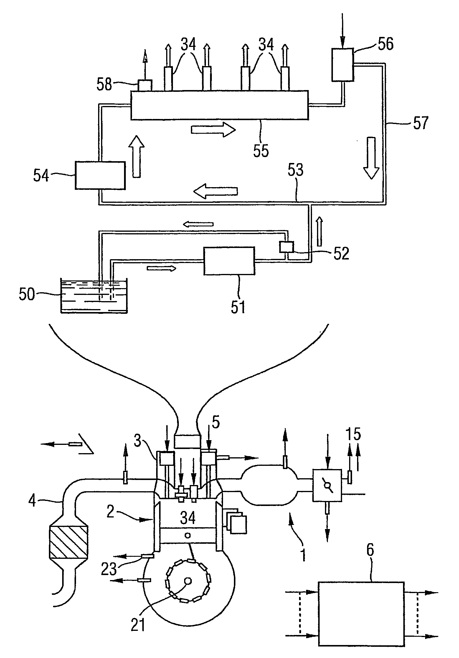
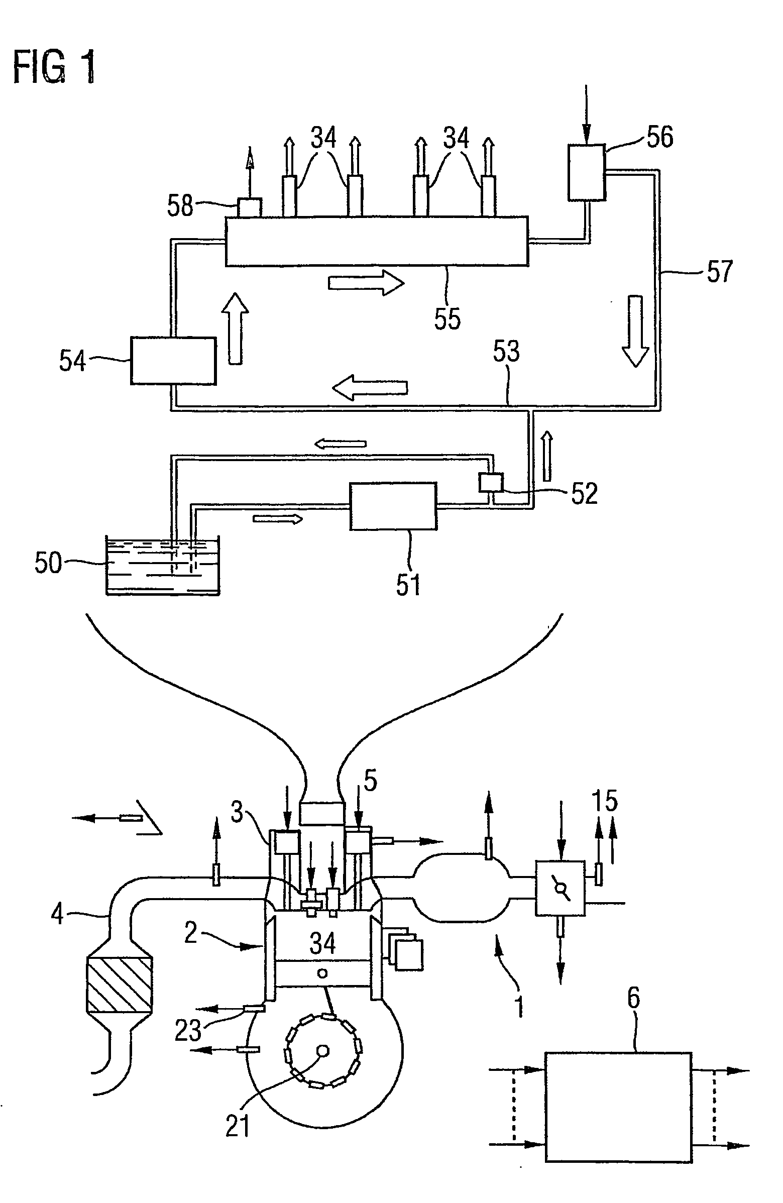
[0013] An internal combustion engine (FIG. 1) comprises an intake tract 1, an engine block 2, a cylinder head 3 and an exhaust tract 4. The engine block comprises a plurality of cylinders having pistons and connecting rods via which they are linked to a crankshaft 21.

[0014] The cylinder head comprises a valve train with an inlet valve, an outlet valve and valve operating mechanisms. The cylinder head 3 additionally comprises an injection valve 34 and a spark plug. Alternatively the injection valve can also be disposed in the intake tract 1.

[0015] A fuel supply device 5 is additionally provided, comprising a fuel tank 50 which is connected to a low pressure pump 51 via a first fuel line. On the output side the low pressure pump 51 is actively connected to an inlet pipe 53 of a high pressure pump 54. In addition, on the output side of the low pressure pump...


PUM


Abstract

A fuel supply device of a combustion engine compromises a fuel pump that pumps fuel into a fuel accumulator, which provides injection valves with fuel and which is connected to a regulator valve that sets the fuel pressure according to an actuating signal (SG). The fuel pressure in the supply device is controlled in such a manner that the actuating signal (SG) is determined according to a desired fuel pressure (FUP_SP) and to quantity that characterizes the dynamics of the flow of the fuel through the regulator valve, and the regulator valve is subsequently controlled by the actuating signal (SG).

Description

CROSS REFERENCE TO RELATED APPLICATION [0001] This application is the US National Stage of International Application No. PCT / EP2004 / 002619, filed Mar. 12, 2004 and claims the benefit thereof. The International Application claims the benefits of German Patent application No. 10318646.8 DE filed Apr. 24, 2003, both of the applications are incorporated by reference herein in their entirety.FIELD OF THE INVENTION [0002] The invention relates to a method for controlling a fuel pressure in a fuel supply device of an internal combustion engine. BACKGROUND OF THE INVENTION [0003] A fuel supply device for an internal combustion engine is known from the Handbuch Verbrennungsmotor (Internal Combustion Engine Manual), Friedrich Vieweg & Sohn Verlagsgesellschaft mbH, Braunschweig / Wiesbaden, 2002, ISBN 3-528-03933-7, page 402. The supply device has a fuel pump which pumps fuel into a fuel accumulator which supplies injection valves with fuel and which is actively connected to a regulator valve wh...

Claims


Application Information

Patent Timeline
IPC IPC(8): F02M59/36F02D35/02F02D41/30F02D41/38
CPCF02D41/123F02D41/3029F02D41/3836F02D2250/31F02D41/3845F02D41/3863
Inventor ESER, GERHARDWIEST, MARTIN
Owner VITESCO TECH GMBH
Why Eureka
Try Eureka