
Methods for minimally invasive vascular access

a vascular access and minimally invasive technology, applied in the field of minimally invasive vascular access, can solve the problems of difficult to precisely identify the location of such deep buried vessels from outside the patient's body, exacerbate the difficulty of accessing these vessels, and difficult to access the vessels

Inactive Publication Date: 2006-10-05
ORQIS MEDICAL
View PDF99 Cites 50 Cited by
  • Summary
  • Abstract
  • Description
  • Claims
  • Application Information

AI Technical Summary

Benefits of technology

[0006] Accordingly, a method of accessing a high flow vessel without causing severe trauma to the patient, while maximizing the size of a cannula to be deployed in the vessel, would be of great benefit to patients undergoing vascular procedures.
[0007] The preferred embodiments of the present methods for minimally invasive vascular access have several features, no single one of which is solely responsible for their desirable attributes. Without limiting the scope of these methods as expressed by the claims that follow, their more prominent features will now be discussed briefly. After considering this discussion, and particularly after reading the section entitled “Detailed Description of the Preferred Embodiments,” one will understand how the features of the preferred embodiments provide advantages, which include the capability to access high flow vessels without causing severe trauma to the patient, while maximizing the size of a vascular instrument to be deployed in the vessel.
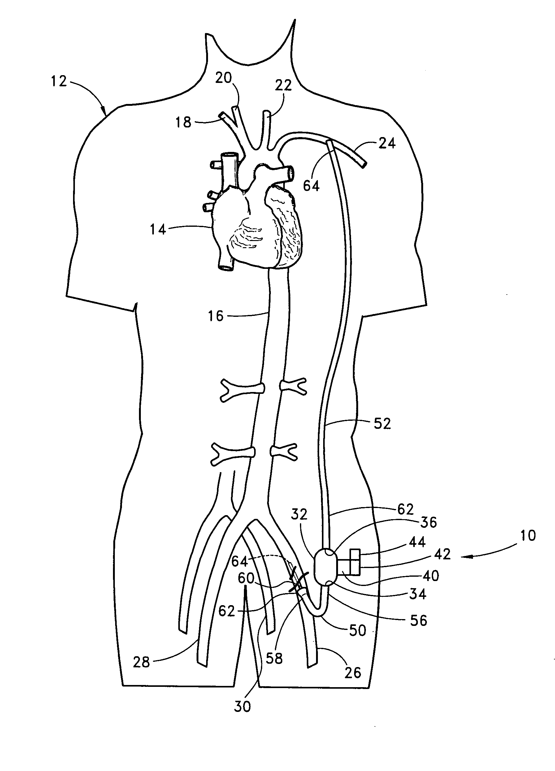
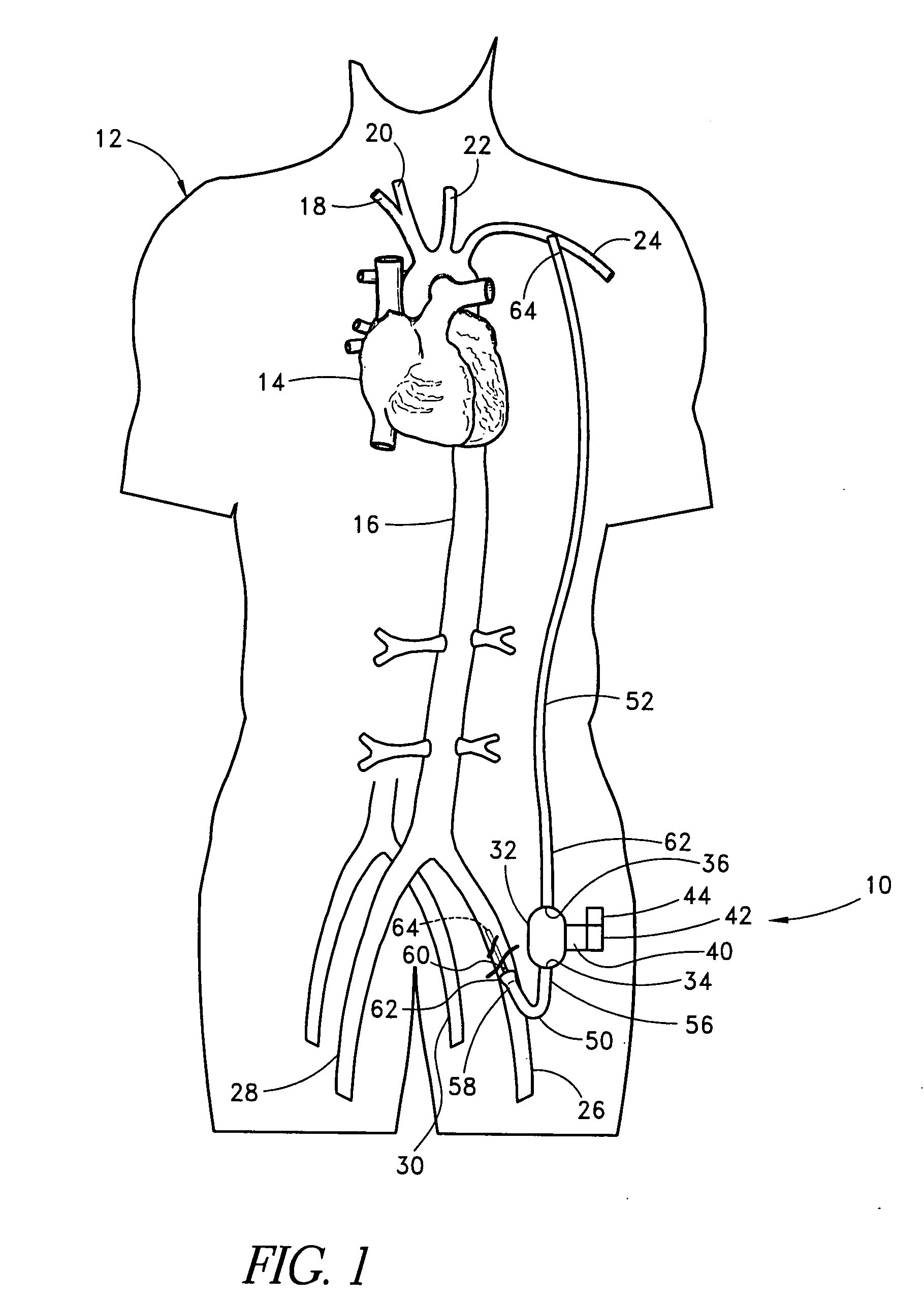
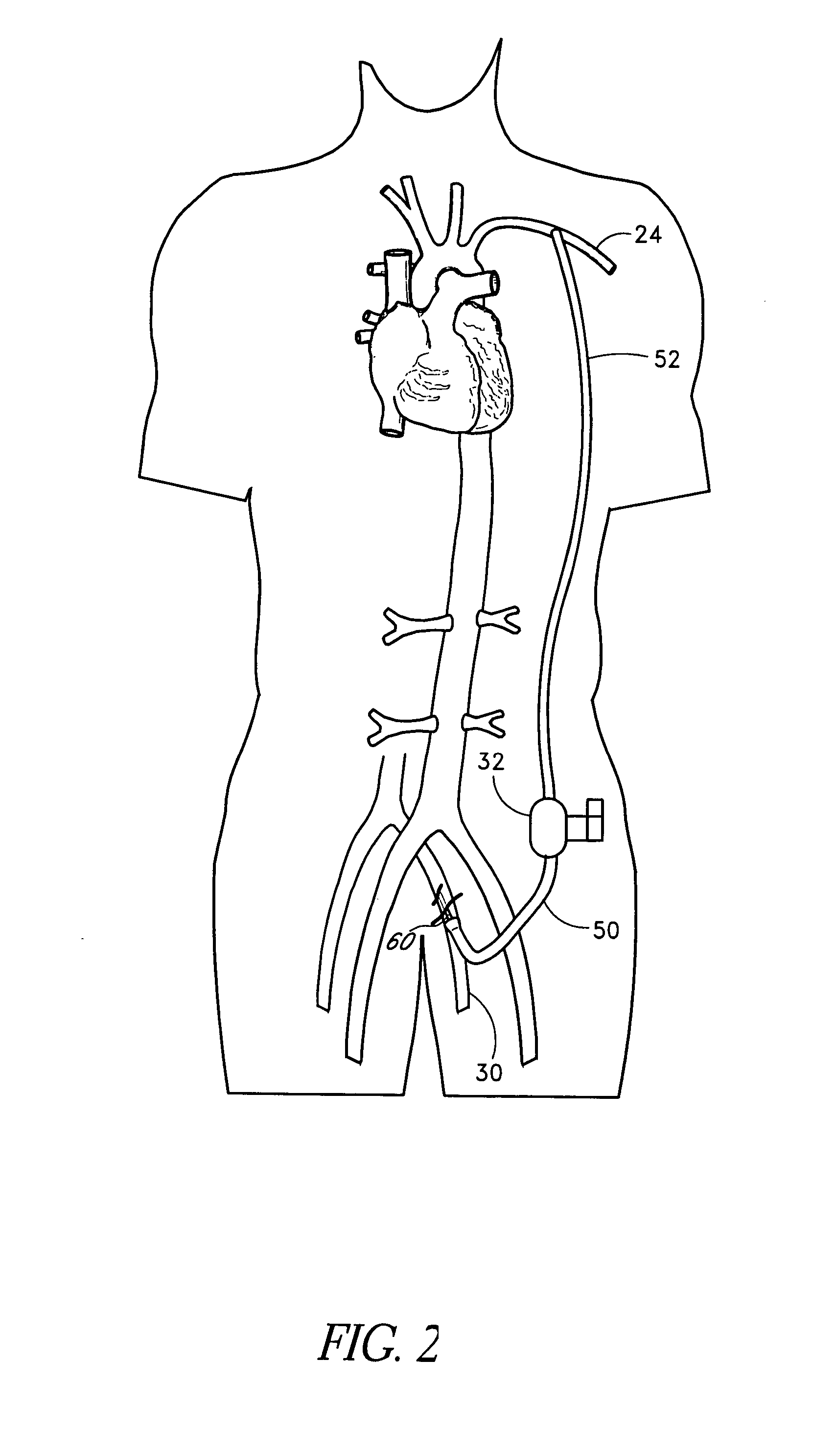
[0008] A preferred method of the present invention provides minimally invasive access to a deeply buried target location in a patient's vasculature. Because the target location is buried deep beneath the patient's skin, a relatively large amount of bodily tissue and / or organs lies between a first percutaneous site and the target location. The present inventive method permits relatively easy access to the target location from a second percutaneous site where the vasculature is located relatively close to the skin. The vasculature at the target location includes a vessel segment with a first perimeter that is larger than a second perimeter of a second vessel segment located near the second percutaneous site. The volumetric flow rate at the first vessel segment is significantly higher than at the second vessel segment in some applications. The method comprises the steps of puncturing a patient's skin and vasculature with a needle at the second percutaneous site, inserting a guide wire through the needle and into the vasculature at the second percutaneous site, removing the needle from the vasculature, advancing the guide wire through the vasculature, with the aid of a visualization apparatus, to the target location, advancing a dilator over the guide wire and inserting the dilator into the vasculature at the second percutaneous site, thereby widening an opening in the vasculature at the second percutaneous site, advancing a tunneling device having a cover through the vasculature, with the further aid of the visualization apparatus, along the guide wire from the second percutaneous site to the target location, the tunneling device being configured to be steerable and having a distal point capable of penetrating the vasculature and tissue between the vasculature and the skin, the cover protecting the vasculature as the device travels through the vasculature, piercing the vasculature wall with the tunneling device at the target location and advancing the tunneling device through the vasculature wall and through the patient's tissue, with the further aid of the visualization apparatus, avoiding sensitive bodily structures, to the first percutaneous site, and inserting a cannula through the first percutaneous site, through the patient's tissue, and into the vasculature at the target location.

Problems solved by technology

Unfortunately, certain high flow vessels, such as those located in the abdominal cavity, are buried deep beneath bodily tissue and organs.
Therefore, these vessels are often difficult to access.
The difficulty in accessing these vessels is exacerbated by the fact that it is difficult to precisely identify the location of such deeply buried vessels from outside the patient's body.
Such a procedure is highly invasive and traumatic for the patient, requiring a lengthy recovery period including hospitalization.
Unfortunately, the relatively low volumetric flow capacity of the femoral artery limits the size of the cannula that can be deployed through that access location.

Method used


Image

  • Methods for minimally invasive vascular access
  • Methods for minimally invasive vascular access
  • Methods for minimally invasive vascular access

Examples


Embodiment Construction

,” one will understand how the features of the preferred embodiments provide advantages, which include the capability to access high flow vessels without causing severe trauma to the patient, while maximizing the size of a vascular instrument to be deployed in the vessel.

[0008] A preferred method of the present invention provides minimally invasive access to a deeply buried target location in a patient's vasculature. Because the target location is buried deep beneath the patient's skin, a relatively large amount of bodily tissue and / or organs lies between a first percutaneous site and the target location. The present inventive method permits relatively easy access to the target location from a second percutaneous site where the vasculature is located relatively close to the skin. The vasculature at the target location includes a vessel segment with a first perimeter that is larger than a second perimeter of a second vessel segment located near the second percutaneous site. The volum...


PUM


Abstract

The present methods provide access to high flow vessels without causing severe trauma for the patient. At the same time, the methods maximize the size of a vascular instrument that can be deployed at the target location. The methods involve tunneling through the patient's tissue to create an access path between a percutaneous access site and the target location by using a second percutaneous site that is generally subcutaneous.

Description

BACKGROUND OF THE INVENTION [0001] 1. Field of the Invention [0002] The present invention relates generally to a method of providing extracorporeal access to a patient's vasculature and, more specifically, to accessing a high volume main vessel by first accessing a low volume peripheral vessel. [0003] 2. Description of the Related Art [0004] When inserting a cannula into a patient, it may be advantageous to access a vessel having a high volumetric flow capacity. For example, when applying the cardiac assist system described in U.S. Pat. No. 6,685,621, it may be advantageous to locate the inflow and outflow cannulae in one or more high flow vessels. The larger the vessel, the larger the vascular instrument that may be deployed there. Unfortunately, certain high flow vessels, such as those located in the abdominal cavity, are buried deep beneath bodily tissue and organs. Therefore, these vessels are often difficult to access. The difficulty in accessing these vessels is exacerbated by...

Claims


Application Information

Patent Timeline
Patent Type & Authority Applications(United States)
IPC IPC(8): A61M31/00A61M37/00A61M60/13A61M60/232A61M60/237A61M60/562A61M60/857
CPCA61M1/10A61M1/101A61M1/3659A61M1/1034A61M1/122A61M25/0194A61M60/414A61M60/148A61M60/232A61M60/237A61M60/562A61M60/13
Inventor SCOTT, MICHAEL J.RADOVANCEVIC, BRANISLAV
Owner ORQIS MEDICAL
Learn More