Semiconductor integrated circuit for communication

a technology of integrated circuits and semiconductors, applied in the direction of pulse automatic control, oscillation generators, resonance circuit tuning, etc., can solve the problem of increasing the inclination of oscillation frequency characteristics to control the voltage of the vco, and achieve the effect of increasing the inclination of oscillation frequency characteristics

Inactive Publication Date: 2006-10-05
RENESAS TECH CORP
View PDF6 Cites 6 Cited by
  • Summary
  • Abstract
  • Description
  • Claims
  • Application Information

AI Technical Summary

Benefits of technology

[0010] An object of the present invention is to provide a semiconductor integrated circuit for communication (radio frequency IC) that includes a PLL circuit having an oscillator to generate a local oscillation signal of a predetermined frequency to be synthesized with a receive signal and a transmission signal, and prevents a PLL loop from being easily unlocked upon fluctuation of VCO oscillation frequencies due to a change in temperature.
[0011] Another object of the present invention is to provide a semiconductor integrated circuit for communication (radio frequency IC) that enables a PLL loop to be locked within a relatively short time after the VCO starts oscillation even when the inclination of oscillation frequency characteristics to control voltage of the VCO is increased.
[0016] According to the above-described means, by increasing the inclination of oscillation frequency characteristics to control voltage of the VCO, a frequency fluctuation range of one band can be widened. Thereby, a PLL loop is prevented from being easily unlocked upon fluctuation of VCO oscillation frequencies due to a change in temperature. Additionally, the PLL loop shifts to a close loop after finding an optimum applied voltage while switching set voltages applied to the VCO by the binary search method. Therefore, even when the inclination of oscillation frequency characteristics to control voltage of the VCO is increased, the PLL loop can be locked in a relatively short time without waiting for it to be naturally locked.
[0017] Preferably, during a shift to a close loop after finding an optimum control voltage by the binary search method, switching is made to a higher control voltage before the loop is closed. Since a PLL circuit including a VCO requires less time required to pull in frequencies when a control voltage is pulled in, in a descending order of control voltages, a time required to lock the loop can be reduced.
[0019] According to the present invention, a PLL loop is prevented from being easily unlocked upon fluctuation of VCO oscillation frequencies due to a change in temperature, and additionally, even when the inclination of oscillation frequency characteristics to control voltage of the VCO is increased, the PLL loop can be locked in a relatively short time after the VCO starts oscillation.

Problems solved by technology

However, there is a problem in that increasing the inclination of oscillation frequency characteristics to control voltage of the VCO increases time after the VOC starts oscillation until a PLL loop is locked.

Method used


Image

  • Semiconductor integrated circuit for communication
  • Semiconductor integrated circuit for communication
  • Semiconductor integrated circuit for communication

Examples


Embodiment Construction

[0027] The following describes embodiments of the present invention with reference to the accompanied drawings.

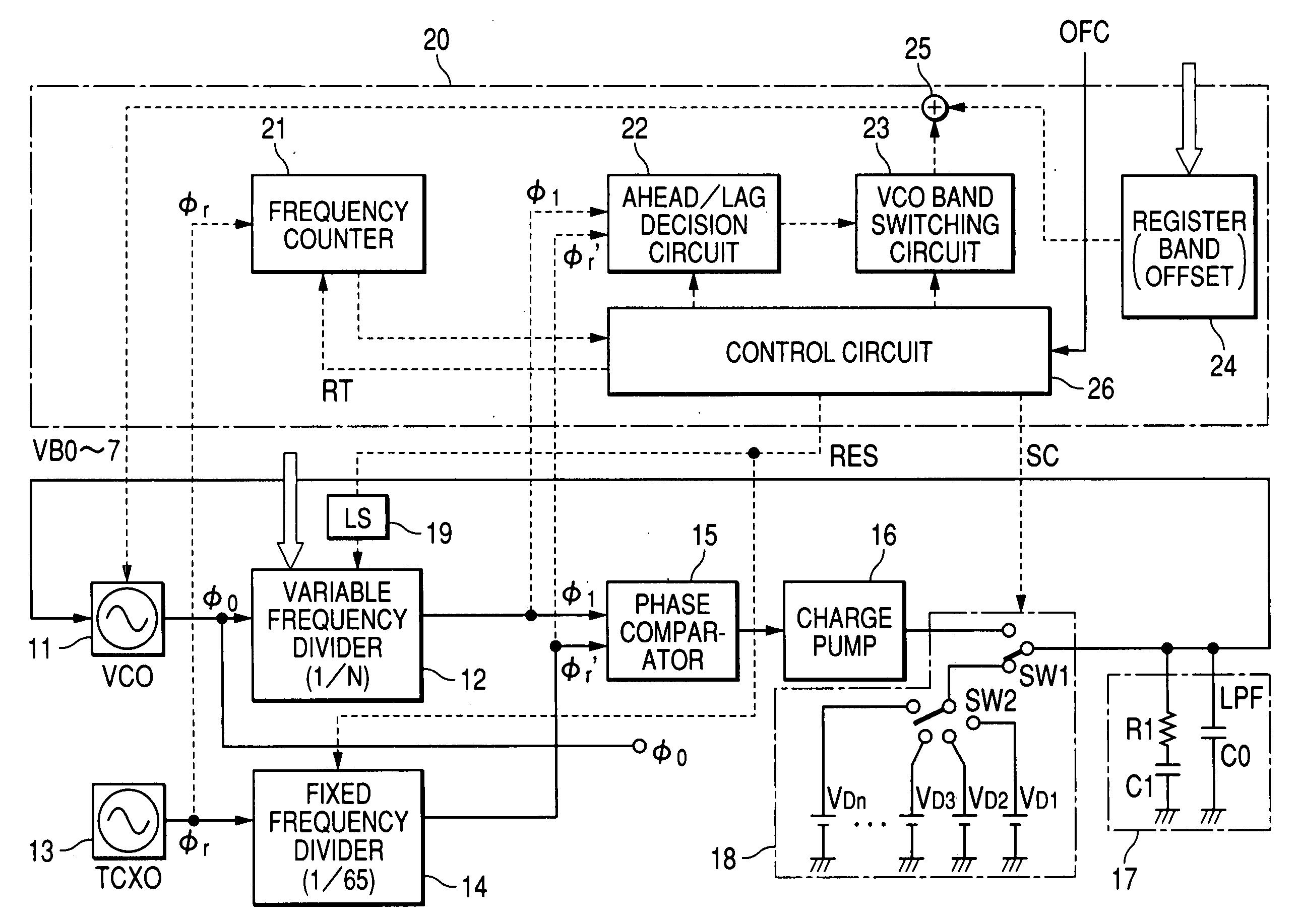
[0028]FIG. 1 shows an embodiment of a PLL circuit according to the present invention having a function for automatically selecting a band used by a VCO, based on frequency information externally set.

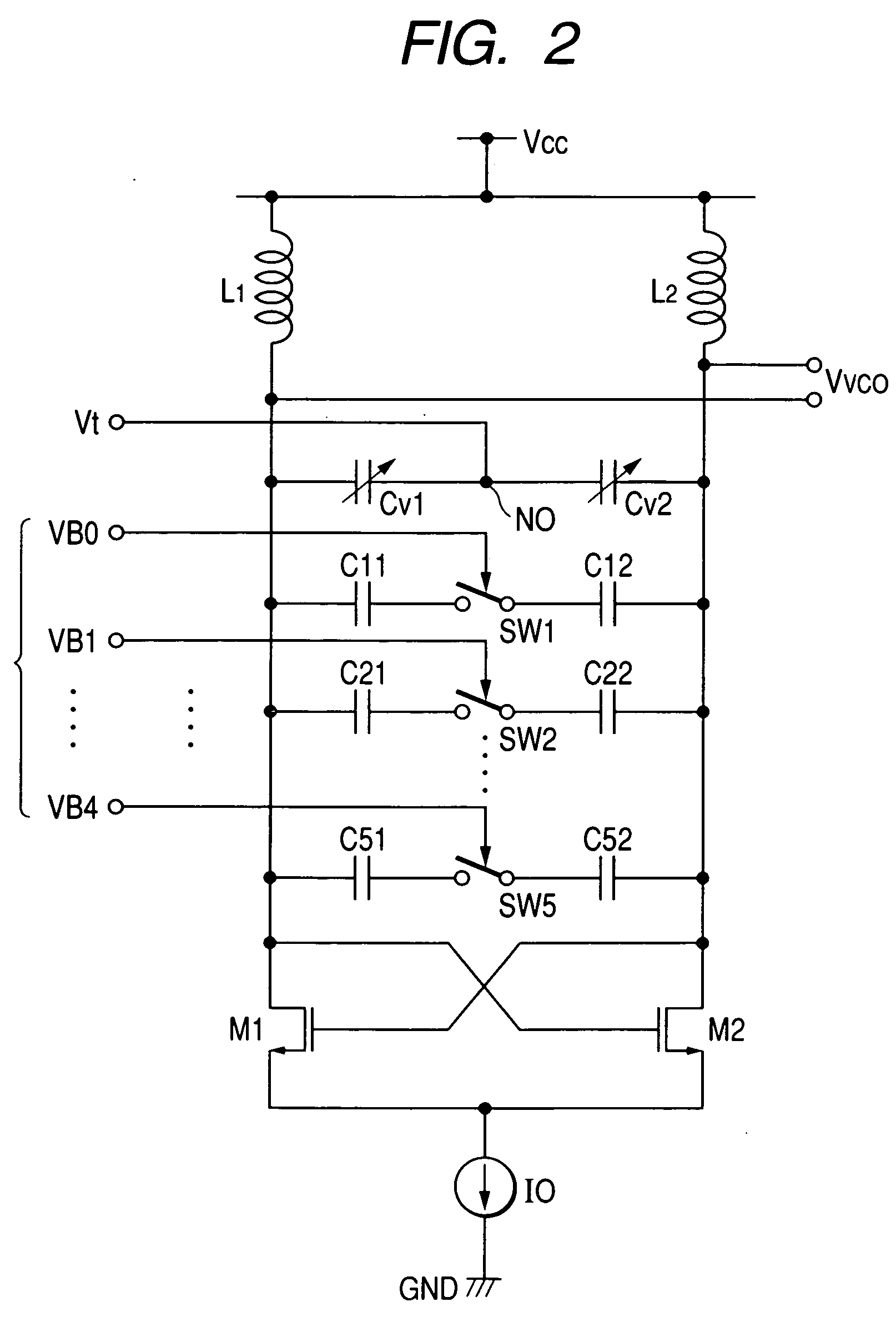
[0029] The PLL circuit of this embodiment includes: a voltage controlled oscillation circuit (VCO) 11; a variable frequency divider 12 that frequency-divides an oscillation signal φ0 of the VCO 11 to 1 / N; a fixed frequency divider 14 that frequency-divides an oscillation signal φr from a reference oscillation circuit 13 that generates a reference oscillation signal φr such as 16 MHz; a phase comparator 15 that detects a phase difference between signals φ1 and φr′ frequency-divided by the variable frequency divider 12 and the fixed frequency divider 14; a charge pump 16 that generates a charging current or discharge current corresponding to the detected phase difference; and a ...


PUM


Abstract

A radio frequency IC includes a PLL circuit and prevents a PLL loop from being easily unlocked upon fluctuation of VCO oscillation frequencies due to a change in temperature. The PLL loop includes a VCO capable of switching oscillation frequency bands, a variable frequency divider, a phase comparison circuit, and a loop filter. A switching switch can apply one of plural predetermined set voltages to the VCO in place of a voltage of the loop filter in an open state in which the loop filter is disconnected from the VCO. The radio frequency IC als has a decision circuit that decides whether the phase of output of the variable frequency divider is ahead of or lags behind that of a reference signal of a predetermined frequency, and an automatic band switching circuit that generates a signal for switching VCO frequency bands, based on output of the decision circuit.

Description

CROSS-REFERENCE TO RELATED APPLICATION [0001] The present application claims priority from Japanese patent application No 2005-093839 filed on Mar. 29, 2005, the content of which is hereby incorporated by reference into this application. BACKGROUND OF THE INVENTION [0002] The present invention relates to technology effectively applied to a PLL (phase locked loop) capable of switching oscillation frequencies of a VCO (voltage controlled oscillator) in stages. For example, the invention relates to technology effectively applied to a PLL circuit that generates an oscillation signal of a predetermined frequency to be synthesized with a receive signal and a transmission signal of radio communication, and a semiconductor integrated circuit for communication including it. [0003] In a radio communication system such as a portable telephone, a semiconductor integrated circuit for radio frequencies (hereinafter referred to a radio frequency IC) that modulates a transmission signal and demodul...

Claims


Application Information

Patent Timeline
IPC IPC(8): H03B5/12H04B1/408
CPCH03B2201/025H03J2200/10H03L7/07H03L7/099H03B5/124H03L7/183H03B5/1228H03B5/1215H03B5/1265H03L7/107
Inventor SATAKE, KUNITOOOSAWA, HIROTAKAIKUTA, ISAOYAMAMOTO, SATORU
Owner RENESAS TECH CORP
Why Eureka
Try Eureka