Voltage converting circuit for electric vehicles

Inactive Publication Date: 2006-10-05
MITSUBISHI FUSO TRUCK AND BUS CORPORATION
View PDF5 Cites 43 Cited by
  • Summary
  • Abstract
  • Description
  • Claims
  • Application Information

AI Technical Summary

Benefits of technology

[0032] According to the voltage converting circuit of the present invention, even in the case where the voltage of the capacitor reaches the operating voltage of the voltage converter when a rush current suppression process is being performed by the precharge circuit, the voltage converter by no means operates because the voltage converter start-up enabling means does not enable start-up of the voltage converter. Because of this, the vehicle drive battery is able to charge the capacitor quickly without supplying electric power to the voltage converter, so that the rush current suppression process can be concluded. Stable precharge control can be performed by avoiding a start-up failure due to the precharge control exceeding a predetermine period of time. In addition, since a rise in voltage of the capacitor becomes stable, the occurrence of excessive rush current can be prevented, without making a misjudgment even in the case where the conclusion of the rush current suppression process is judged by a lapse of time or a voltage rise rate.
[0034] In this case, the capacitor is charged while preventing the occurrence of excessive rush current by suitable electric resistance. This makes it possible to perform the rush current suppression process with a simpler construction.
[0036] In this case, the voltage converter start-up means comprises a switch through which the start-up enabling signal is input to the voltage converter, and which synchronizes the main contactor. This makes it possible to reliably prevent the voltage converter from operating during the rush current suppression process with a simpler construction.

Problems solved by technology

However, if a direct current from the vehicle drive battery is input to the inverter via the main contactor, an extremely high current (rush current) will flow into the aforementioned capacitor in a short time and therefore damage, such as the contact of the main contactor being melted, will be caused.
However, in the aforementioned prior art, it sometimes takes a much longer time than normal to start and conclude the precharge control.
As a result, trouble such as the start-up failure of the DC / DC converter 101 sometimes occurs.
This can cause the aforementioned trouble.
As a result, trouble such as the start-up failure of the vehicle drive motor 109 is caused.
This can cause misjudgment if the conclusion of the precharge control is judged based on the condition of a lapse of time, a voltage rise rate, or the like.

Method used


Image

  • Voltage converting circuit for electric vehicles
  • Voltage converting circuit for electric vehicles
  • Voltage converting circuit for electric vehicles

Examples


Embodiment Construction

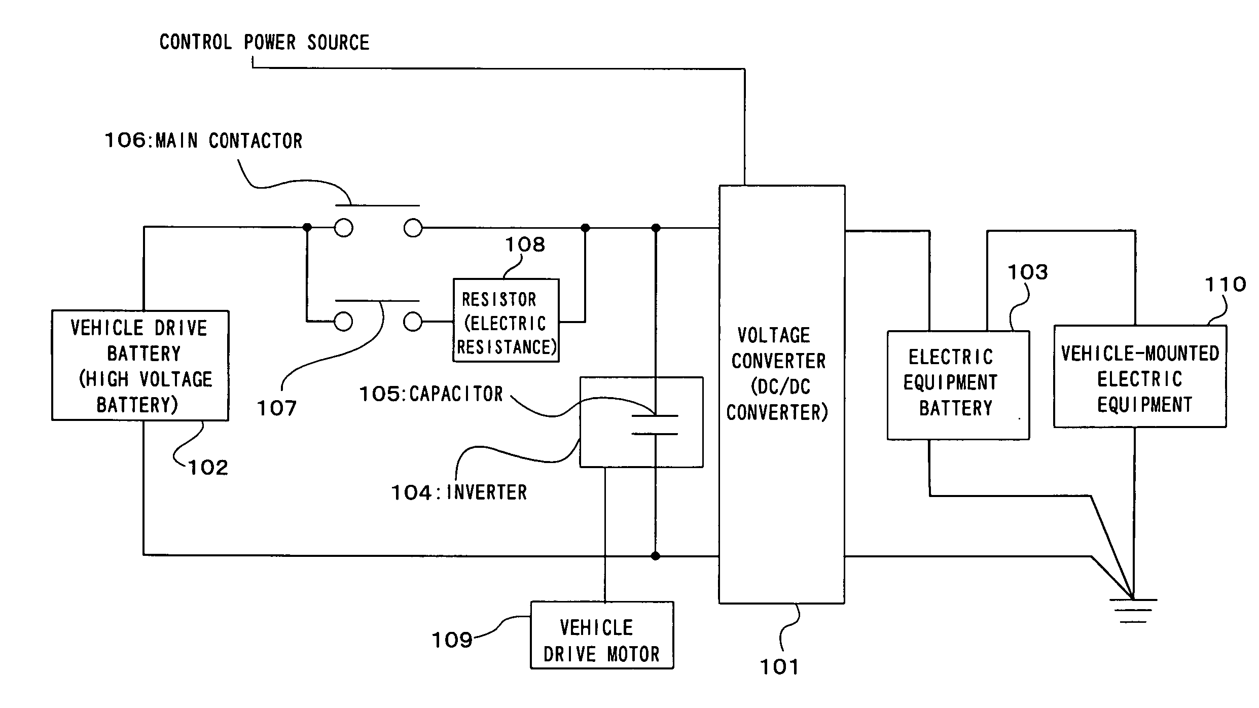
[0044] Referring to FIGS. 1 to 3, there is shown a voltage converting circuit for electric vehicles constructed in accordance with a preferred embodiment of the present invention. In FIG. 1, the same parts as the prior art in FIG. 4 are given the same reference numerals.

[0045] As shown in FIG. 1, the voltage converting circuit of the preferred embodiment is equipped with a vehicle drive motor 109; a high-voltage (e.g. 500V) vehicle drive battery (high voltage battery) 102; an inverter 104 having a capacitor 105; a DC / DC converter (voltage converter) 101; and a contactor circuit 120 including a precharge circuit.

[0046] The vehicle drive motor 109 is connected with the vehicle drive battery 102 through the inverter 104. An electric equipment battery 103 is connected to the vehicle drive battery 102 through the DC / DC converter 101 in parallel with the inverter 104. The electric equipment battery 103 is further connected to vehicle-mounted electric equipment 110.

[0047] The contactor ...


PUM


Abstract

A voltage converting circuit for electric vehicles that is capable of stably performing precharge control from a high voltage battery to an inverter. The voltage converting circuit includes a high voltage battery for supplying electric power to a vehicle drive motor; and an inverter, which is interposed between the high voltage battery and the vehicle drive motor and has a capacitor, for converting a direct current, supplied from the high voltage battery, to an alternating current and supplying to the vehicle drive motor. The voltage converting circuit further includes a voltage converter, connected to the high voltage battery in parallel with the inverter, for converting a voltage of the high voltage battery to a low voltage and outputting the low voltage; a contactor circuit, interposed between the high voltage battery and the inverter, for performing a process of suppressing rush current relative to the inverter when supplying electric power of the high voltage battery to the vehicle drive motor; and voltage a converter start-up enabling units and for enabling start-up of the voltage converter when a conclusion of the suppression process performed by the contactor circuit is sensed.

Description

BACKGROUND OF THE INVENTION [0001] (1) Field of the Invention [0002] The present invention relates to a voltage converter for converting the electric power of a high voltage battery, equipped in an electric vehicle, to a low voltage and charging a low voltage battery. [0003] (2) Description of the Related Art [0004] Electric vehicles including a hybrid electric vehicle are typically equipped with a vehicle drive battery (high voltage battery) for storing a DC power of relatively high voltage (e.g. about 500 V), an inverter for converting the DC power of the vehicle drive battery to AC power, and a vehicle drive motor that is driven by the AC power converted by the inverter. By rotating driving wheels connected to the output shaft of the vehicle drive motor so that power can be transferred, the vehicle is caused to travel. [0005] In addition to the vehicle drive battery, electric vehicles are further equipped with an electric equipment battery (low voltage battery) for storing a DC p...

Claims


Application Information

Patent Timeline
IPC IPC(8): H02P5/00B60L50/15
CPCB60L1/02B60L1/14Y02T10/7066H02M1/36Y02T10/7005B60L11/1868B60L58/20Y02T10/70B60L50/50
Inventor HORII, YUSUKE
Owner MITSUBISHI FUSO TRUCK AND BUS CORPORATION
Why Eureka
Try Eureka