Image forming apparatus
a technology of image forming apparatus and forming tube, which is applied in the direction of digital output to print units, instruments, electrographic processes, etc., can solve the problems of increasing electromagnetic radiation noise may possibly leak to the outside of the apparatus, etc., and achieve the effect of reducing the leakage of electromagnetic radiation nois
- Summary
- Abstract
- Description
- Claims
- Application Information
AI Technical Summary
Benefits of technology
Problems solved by technology
Method used
Image

Examples
first embodiment
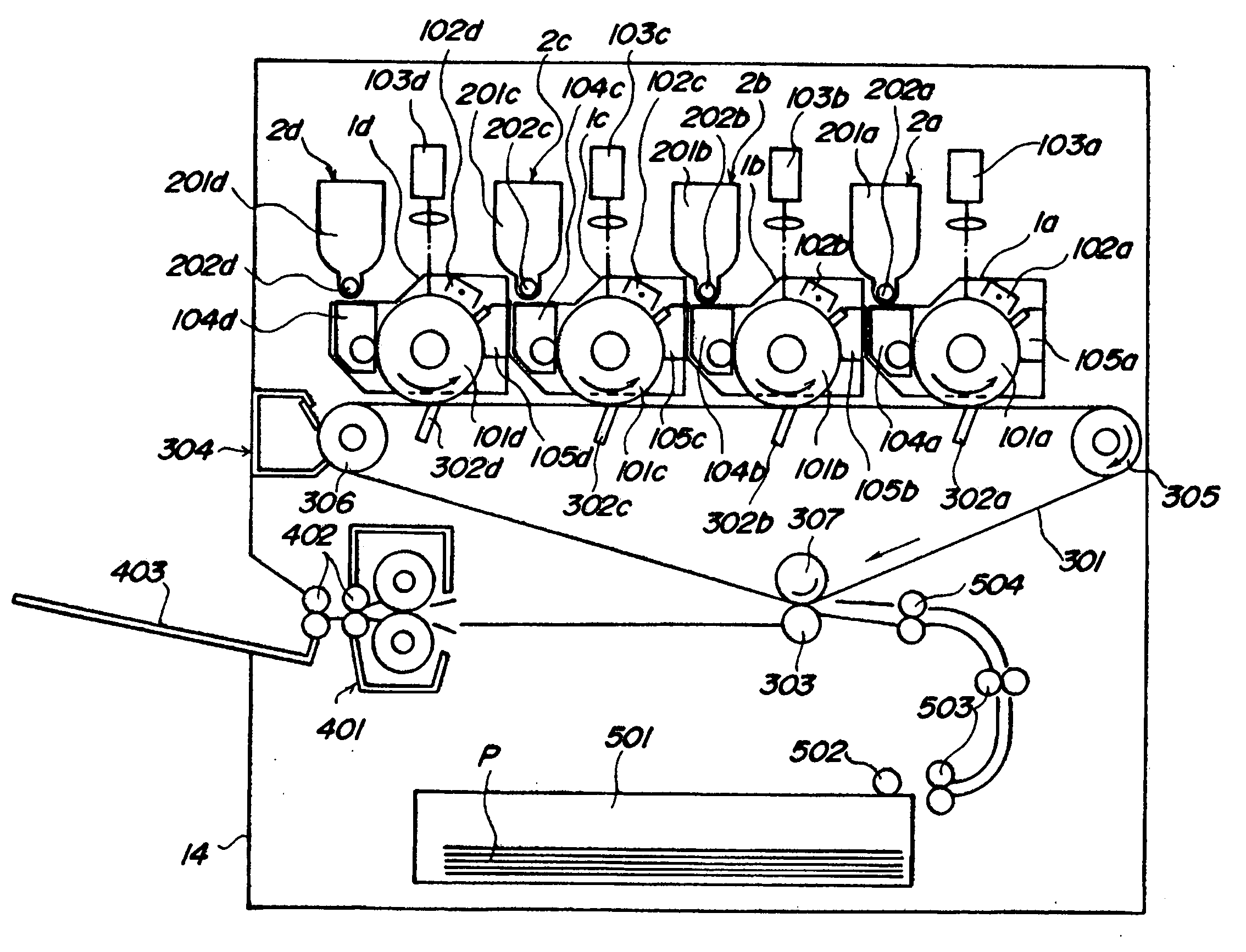
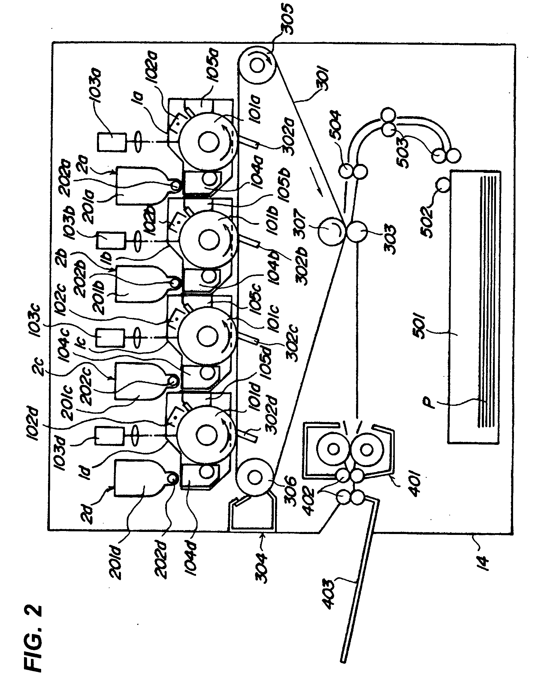
[0033] An image forming apparatus according to a first embodiment of the present invention based on the drawings will be described. FIG. 2 is a schematic sectional view of an electrographic color printer by way of an example of the image forming apparatus.
[0034] An electrographic color printer as shown in FIG. 2 comprises process cartridges1 (1a, 1b, 1c, 1d) each of which can be independently and detachably loaded in the main body and toner cartridges 2 (2a, 2b, 2c, 2d) that use a container of developer as a cartridge.
[0035] Around photosensitive drums 101 (101a, 101b, 101c, 101d) as an image bearing member, are arranged charging devices 102 (102a, 102b, 102c, 102d) that uniformly charge surfaces of the photosensitive drums 110, charging devices 102 (102a, 102b, 102c, 102d) that uniformly charges surfaces of the photosensitive drums 101, exposure devices 103 (103a, 103b, 103c, 103d) that expose image information onto the photosensitive drums 101, development apparatuses 104 (104a,...
second embodiment
[0088] Here, using FIG. 16 and FIG. 17, a second embodiment of the present invention will be described. The present embodiment differs from the first embodiment described above in that the RFID tags and the reader / writer, and the shielded area made by the shield member in which they are arranged are placed in front of the apparatus main body. Thus, only the characteristic part is described, and skip other parts as they are similar to the first embodiment described above.
[0089]FIG. 16 is a side sectional view showing the process cartridge 1 loaded into the apparatus main body, being equivalent to FIG. 6 in the first embodiment.
[0090] As shown in FIG. 16, on the resin container 115 of the process cartridge 1 according to the present embodiment is provided a base 125 that protrudes more forward than the unit front side plate 111. Then, on the base 125 is arranged the RFID tag as an IC tag.
[0091] On the one hand, the front cover 35 of the apparatus main body is provided with the shie...
third embodiment
[0096] Here, using FIG. 18 and FIG. 19, a third embodiment of the present invention will be described. This embodiment differs from the first embodiment described above in that the RFID tags are arranged in positioning pins of the process cartridge. Thus, only the characteristic part is described, and skip other parts as they are similar to the first embodiment described above.
[0097]FIG. 18 is a side sectional view of the main components showing the process cartridge 1 loaded into the apparatus main body 14.
[0098] As shown in FIG. 18, in the present embodiment, the positioning pin 114 is defined by projecting a part of the resin container 115 of the process cartridge 1. Then, at the top end of the positioning pin 114 the RFID tag as an IC tag is integrally molded.
[0099]FIG. 19 shows detailed sectional view of the positioning pin unit at the process cartridge.
[0100] As shown in FIG. 19, the RFID tag 120 is contained in a capsule 124 of thermal insulator. This is to protect the RF...
PUM
 Abstract
Description
Claims
Application Information
 - R&D
- Intellectual Property
- Life Sciences
- Materials
- Tech Scout
- Unparalleled Data Quality
- Higher Quality Content
- 60% Fewer Hallucinations
Browse by: Latest US Patents, China's latest patents, Technical Efficacy Thesaurus, Application Domain, Technology Topic, Popular Technical Reports.
© 2025 PatSnap. All rights reserved.Legal|Privacy policy|Modern Slavery Act Transparency Statement|Sitemap|About US| Contact US: help@patsnap.com