
Method for using CVD process to encapsulate coil in a magnetic write head

a technology of encapsulation and magnetic write head, which is applied in the field of methods, can solve the problems of undesirable voids between the coils, poor match of the thermal expansion characteristic of the other materials in the head, and limited material and design that can be used for the magnetic sensor, so as to improve the thermal protrusion characteristics and enhance chemical vapor deposition.

Inactive Publication Date: 2006-09-28
WESTERN DIGITAL TECH INC
View PDF9 Cites 3 Cited by
  • Summary
  • Abstract
  • Description
  • Claims
  • Application Information

AI Technical Summary

Benefits of technology

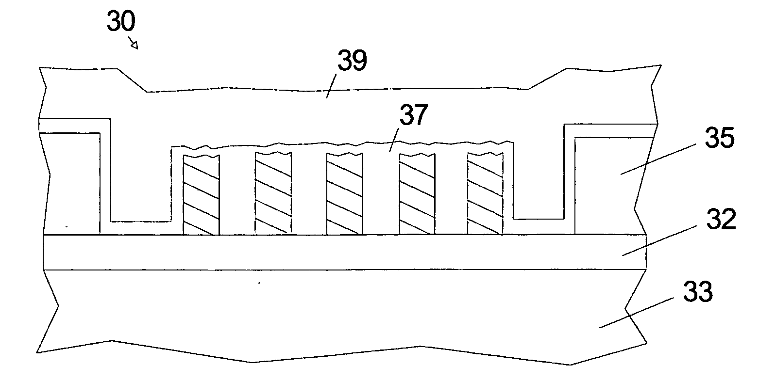
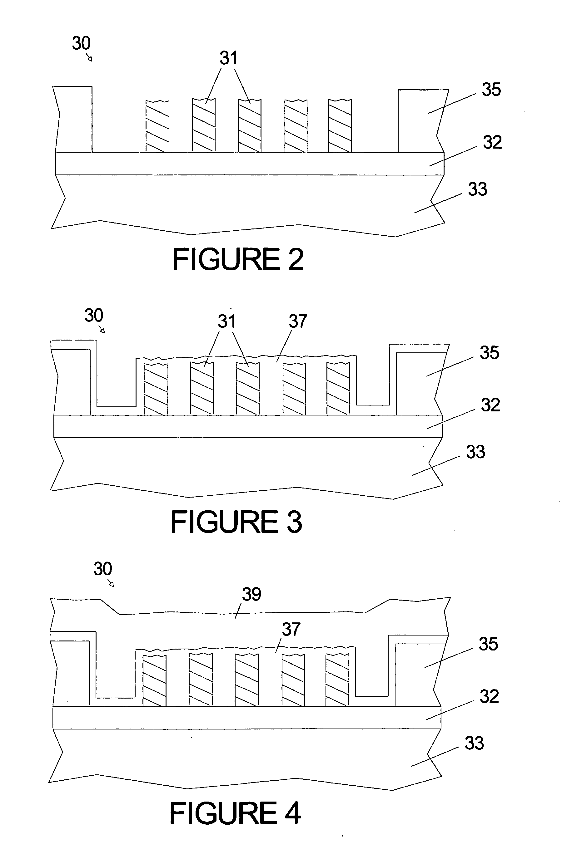
[0006] Applicant discloses a method for fabricating a magnetic write head with a coil with a high aspect ratio using a Chemical Vapor Deposition process such as Atomic Layer Deposition (ALD), High Speed ALD, Plasma Enhanced ALD (PEALD), Plasma Enhanced Chemical Vapor Deposition (PECVD) or Low Pressure Chemical Vapor Deposition (LPCVD) to form encapsulating films over the coils without voids. Materials which can be used for encapsulation include Al2O3, SiO2, AlN, Ta2O5, HfO2, ZrO2, and YtO3. The use of an ultra-conformal deposition process allows the pitch of the coils to be smaller than it is possible in the prior art. The method according to the invention also allows materials with a smaller coefficient of thermal expansion than hardbake photoresist to be used with resulting improvements in thermal protrusion characteristics.

Problems solved by technology

This temperature limits the materials and designs that can be used for the magnetic sensor.
The hardbake material also has a thermal expansion characteristic which is a poor match for the other materials in the head.
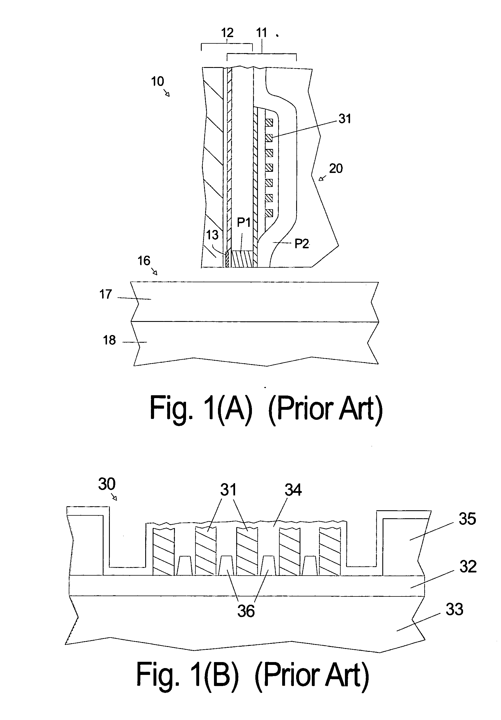
In addition, for high aspect ratio coils, where the height of the coil is several times the spacing (pitch) between the coil turns other fill techniques such as sputtering can result in undesirable voids between the coil turns. FIG. 1(B) illustrates such a problem.

Method used


Image

  • Method for using CVD process to encapsulate coil in a magnetic write head
  • Method for using CVD process to encapsulate coil in a magnetic write head
  • Method for using CVD process to encapsulate coil in a magnetic write head

Examples


Embodiment Construction

[0013] It is conventional for thousands of heads to be manufactured simultaneously on a single wafer. For simplicity the following will describe the actions or structures for a single head, but it is to be understood that the process steps are performed over the entire wafer and are, therefore, forming structures for thousands of heads simultaneously. The invention relates to the write head portion of the magnetic transducer and does not place limits on the type of read head that can be used with it. Typically the read head portion of the transducer is fabricated first, but transducers with the write head portion fabricated first have been described in the prior art. A write head according to the invention may be fabricated before or after the read head portion of the transducer.

[0014] The relative sizes of the components shown in the figures are not presented according to scale, since the large range of sizes would make the drawings unclear. The relative sizes / thickness of the com...


PUM

PropertyMeasurementUnit
magneticaaaaaaaaaa
magnetic transitionsaaaaaaaaaa
magnetic domainsaaaaaaaaaa

Abstract

Applicant discloses a method for fabricating a magnetic write head with a coil with a high aspect ratio using a Chemical Vapor Deposition process such as Atomic Layer Deposition (ALD), High Speed ALD, Plasma Enhanced ALD (PEALD), Plasma Enhanced Chemical Vapor Deposition (PECVD) or Low Pressure Chemical Vapor Deposition (LPCVD) to form encapsulating films over the coils without voids. Materials which can be used for encapsulation include Al2O3, SiO2, AlN, Ta2O5, HfO2, ZrO2, and YtO3. The use of an ultra-conformal deposition process allows the pitch of the coils to be smaller than it is possible in the prior art. The method according to the invention also allows materials with a smaller coefficient of thermal expansion than hardbake photoresist to be used with resulting improvements in thermal protrusion characteristics.

Description

FIELD OF THE INVENTION [0001] The invention relates to the field of magnetic transducers (heads) having inductive write heads and more particularly to the structure of and the process for making the pole pieces for the write head. BACKGROUND OF THE INVENTION [0002] In a typical prior art magnetic disk recording system a slider containing magnetic transducers for reading and writing magnetic transitions flies above the disk while it is being rotated by a spindle motor. The disk includes a plurality of thin films and at least one ferromagnetic thin film in which the recording (write) head records the magnetic transitions in which information is encoded. The magnetic domains in the media on can be written longitudinally or perpendicularly. Perpendicular magnetic recording is considered to be superior to longitudinal magnetic recording for ultra-high density magnetic recording. The increase demand for higher areal density has correspondingly led to increase demand to explore ways to red...

Claims


Application Information

Patent Timeline
Patent Type & Authority Applications(United States)
IPC IPC(8): G11B5/127
CPCG11B5/17G11B5/3133G11B5/3136Y10T29/49064Y10T29/49041Y10T29/4906G11B5/3163
Inventor HSIAO, RICHARDJAYASEKARA, WIPUL PEMSIRIZOLLA, HOWARD GORDON
Owner WESTERN DIGITAL TECH INC
Learn More