Heater and temperature measurement system

a temperature measurement and temperature technology, applied in the field of heaters and temperature measurement systems, can solve problems such as difficult contact between a thermocouple and a sample, spatial problems with a separate thermocouple or temperature measurement, and difficult to detect the temperature, so as to achieve the effect of maximum sensitivity of temperature detection

Inactive Publication Date: 2006-09-28
COLLEGE OF WILLIAM & MARY
View PDF3 Cites 1 Cited by
  • Summary
  • Abstract
  • Description
  • Claims
  • Application Information

AI Technical Summary

Benefits of technology

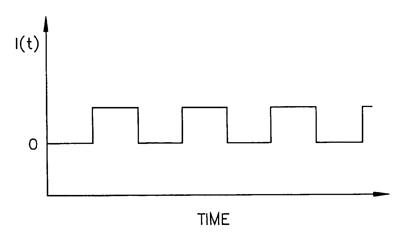
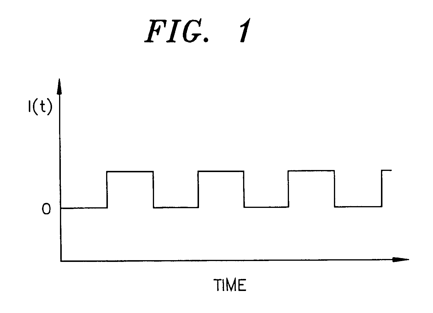
[0007] We have produced a resistance heater made of selected high-resistance thermocouple elements wherein the junction is located at a strategic position of interest for temperature measurement. An alternating cycle (e.g., a square wave pattern) can be used such that the device operates in the heating mode when the high current power is applied and operates in the temperature measurement mode during power off periods. The power off mode may require some time to settle out (because the square wave is not perfectly square in practice), and then the thermocouple (TC) voltage is detected and measured. Ideally, the control circuitry employs a relatively noise-free power off to maximize sensitivity of temperature detection.
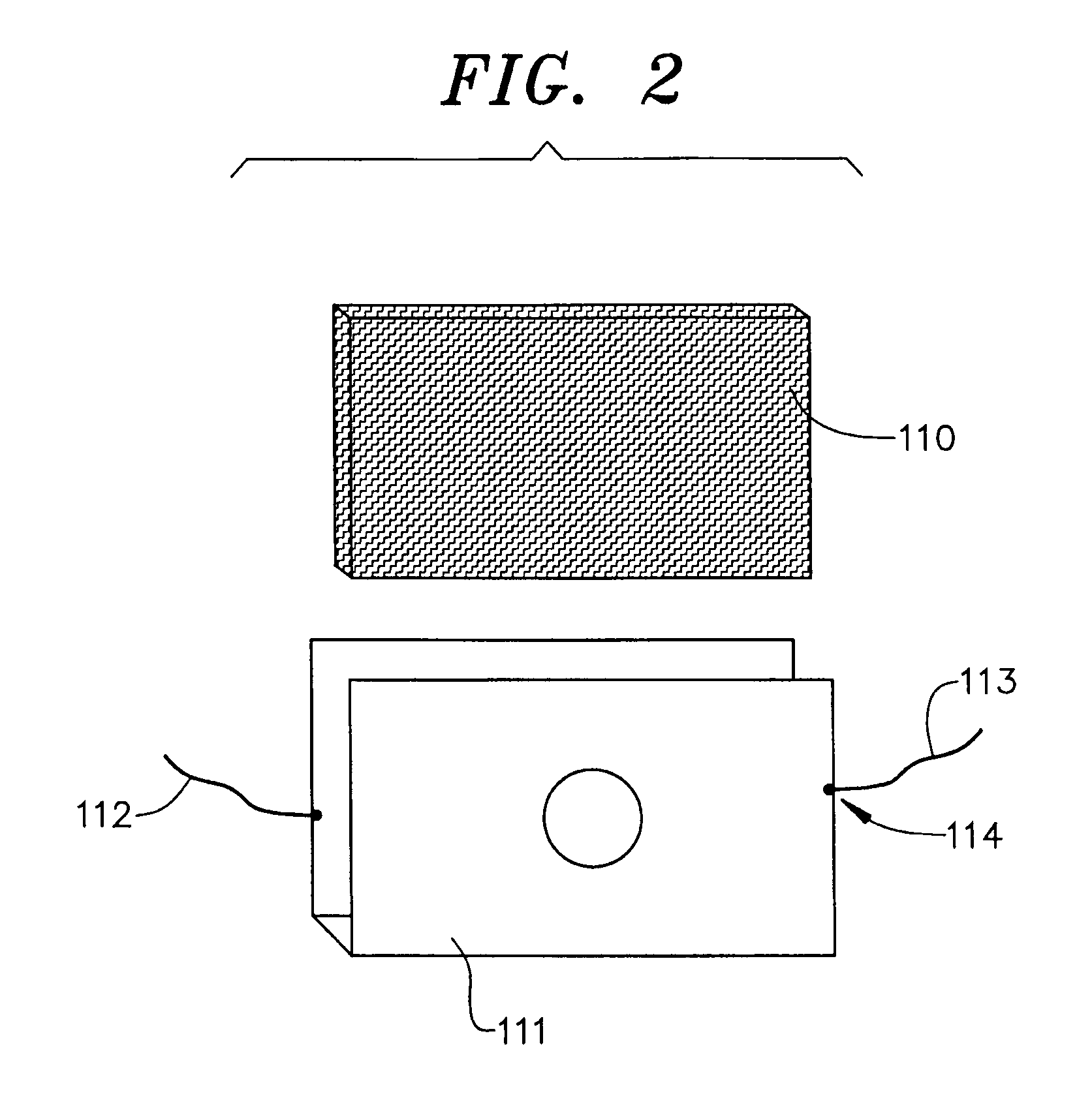
[0008] In one embodiment, the invention is a thin-sheet heater with a thermocouple wire as one of the two leads. The invention allows for a time-controlled power supply / heater and voltmeter all within the leads. This device uses the same lead for heat and temperature control, thereby allowing simple electronics and a low-cost electrical feed through to a vacuum system.

Problems solved by technology

In addition to the expense of these individual components and the space required to accommodate the additional apparatus, spatial problems with a separate thermocouple or temperature measurement may occur in the application.
This is particularly common and problematic in small, complex, and crowded regions.
For example, in temperature desorption spectroscopy, when testing is conducted under vacuum that requires heating, contact between a thermocouple and the sample may be difficult.
The deficiency in the button heater is that it does not have a thermocouple.
Accordingly, complex electronics are required, with corresponding high costs.

Method used


Image

  • Heater and temperature measurement system
  • Heater and temperature measurement system
  • Heater and temperature measurement system

Examples


examples

[0029] The present invention may be better understood with reference to the following examples. These examples are intended to be representative of specific embodiments of the invention, and are not intended as limiting the scope of the invention.

[0030] A prototype heater / thermocouple was built in accordance with the circuit diagrams in FIGS. 4 and 5. The prototype device was used to record the following data points provided in Table 1 and Table 2. The column headings in Tables 1 and 2 are defined below.

[0031] The heading “Control Setting” refers to the value of a 10-turn pot on the front panel of the device. This corresponds to a 0-10V input range at the back panel connector between pins A (positive) and E (Ground).

[0032] The heading “Current” refers to the current read from the front panel of the prototype's power supply (HP6264B). The maximum current of 7.2 Å represents a peak current of about 200 Å.

[0033] The heading “K-type tc” refers to the temperature of the prototype dev...


PUM

PropertyMeasurementUnit
Temperatureaaaaaaaaaa
Electrical resistanceaaaaaaaaaa

Abstract

Current industrial and research applications that utilize resistance heating and temperature measurement require separate power and temperature connections, typically two for each. Such applications require separate assemblies and control. We describe herein a combined unit utilizing a thermocouple wire as one of its two leads. The resulting device requires only two connections and one control. An alternating cycle can be used to apply heating power, and temperature measurements are made during the power off portion of the cycle.

Description

CROSS-REFERENCE TO RELATED APPLICATIONS [0001] This application is based upon and claims priority to U.S. Provisional Patent Application No. 60 / 631,441, filed Nov. 29, 2004, the contents of which are incorporated by reference in their entirety. STATEMENT REGARDING FEDERALLY SPONSORED RESEARCH OR DEVELOPMENT [0002] This invention was made with U.S. Government support under grant N00014-02-1-0711 awarded by the Office of Naval Research. The U.S. Government may have certain rights in this invention.BACKGROUND OF THE INVENTION [0003] Resistance heating (passage of current through a high resistance wire to generate a high I2R loss in the form of heat) is a commonly used method for raising the temperature of devices in many different technologies, e.g., various electric heaters, samples, substrates, molds, injection mold guns, chambers, stages, and platens. In these applications, a separate device from the heater is usually required for measurement of the temperature (e.g., thermocouples,...

Claims


Application Information

Patent Timeline
IPC IPC(8): F27B14/00
CPCB22D17/2038F27D11/02F27D19/00F27D21/0014
Inventor OUTLAW, RONALD A.HOLLOWAY, BRIAN C.
Owner COLLEGE OF WILLIAM & MARY
Why Eureka
Try Eureka