
Devices, systems and method for calibration of systems

a technology of system calibration and calibration method, applied in the direction of liquid/fluent solid measurement, testing/calibration for volume flow, instruments, etc., can solve the problems of equipment failure, fluid path element failure, and difficulty in direct measurement of fluid pressure in a syringe, so as to reduce the downtime of injection equipment and medical staff, the time to conduct pressure calibration can be reduced, and the effect of stable and repeatable calibration

Inactive Publication Date: 2006-09-28
MEDRAD INC.
View PDF7 Cites 35 Cited by
  • Summary
  • Abstract
  • Description
  • Claims
  • Application Information

AI Technical Summary

Benefits of technology

[0018] The calibration devices, systems and method of the present invention provide a number of advantages over current techniques. For example, in an injection system, the time to conduct a pressure calibration can be reduced from, for example, approximately ½ hour to a matter of seconds (for example, approximately 15 seconds), resulting in a significant reduction of downtime of injection equipment and medical staff. Moreover, the calibration devices, systems and methods of the present invention result in periodic “in the field” pressure calibrations that are generally as accurate as the “production” calibration occurring at the time of manufacture. In that regard, automation of the calibration process (via the injector and associated software) eliminates manual intervention, resulting in stable and repeatable calibrations. The calibration devices, systems and methods of the present invention are also less complex for production and field personnel. In general, existing injectors are readily retrofitted to practice the calibration methods of the present invention.

Problems solved by technology

In addition to potential hazards to the patient (for example, vessel damage) and potential degradation of the diagnostic and / or therapeutic utility of the injection fluid, excessive pressure can lead to equipment failure.
If the injector causes pressure in the fluid path to rise above the burst strength of a disposable fluid path element, the fluid path element will fail.
Direct measurement of fluid pressure in a syringe is often difficult.
Moreover, errors or inaccuracies can be introduced by the calibrating technician.

Method used


Image

  • Devices, systems and method for calibration of systems
  • Devices, systems and method for calibration of systems

Examples


Embodiment Construction

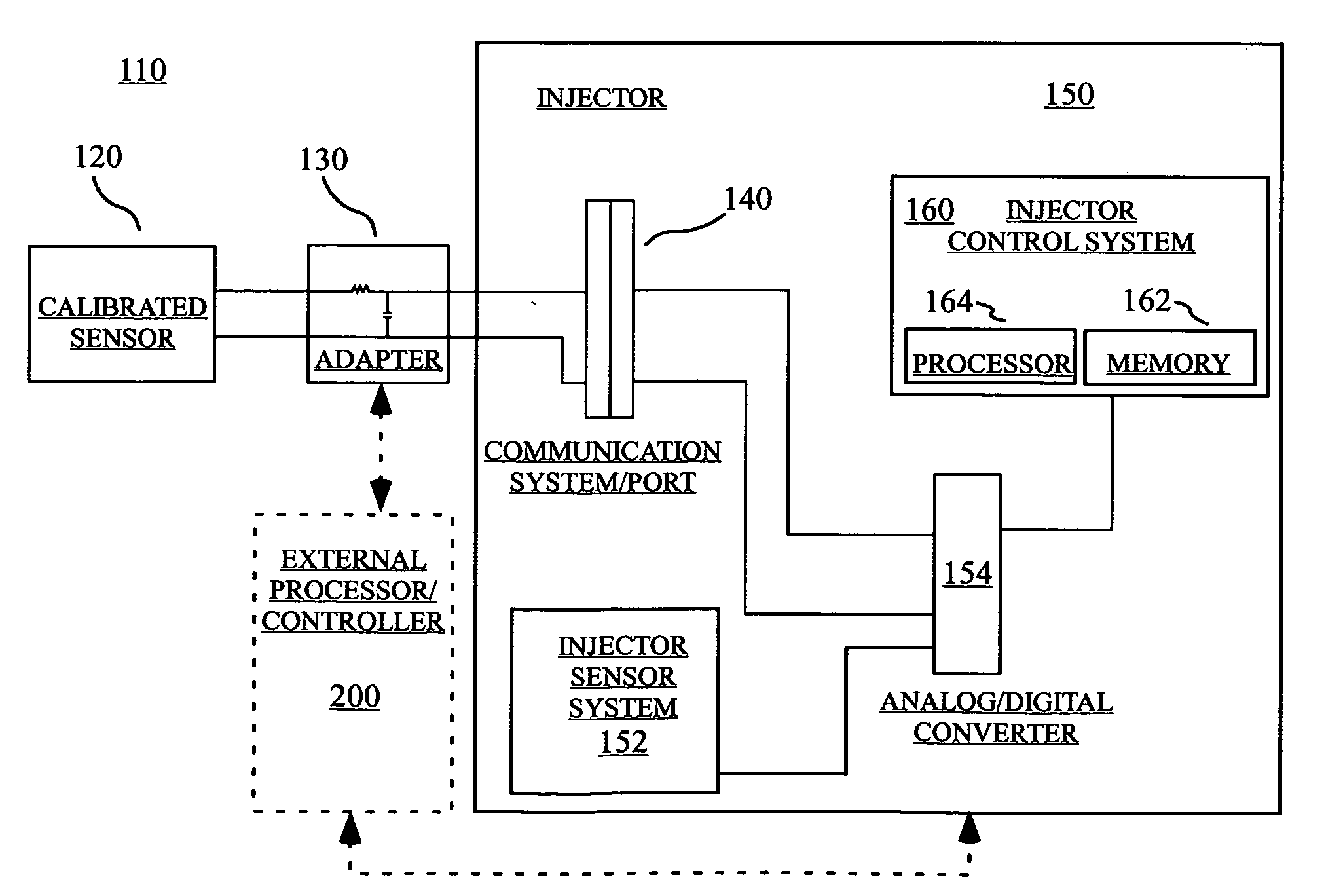
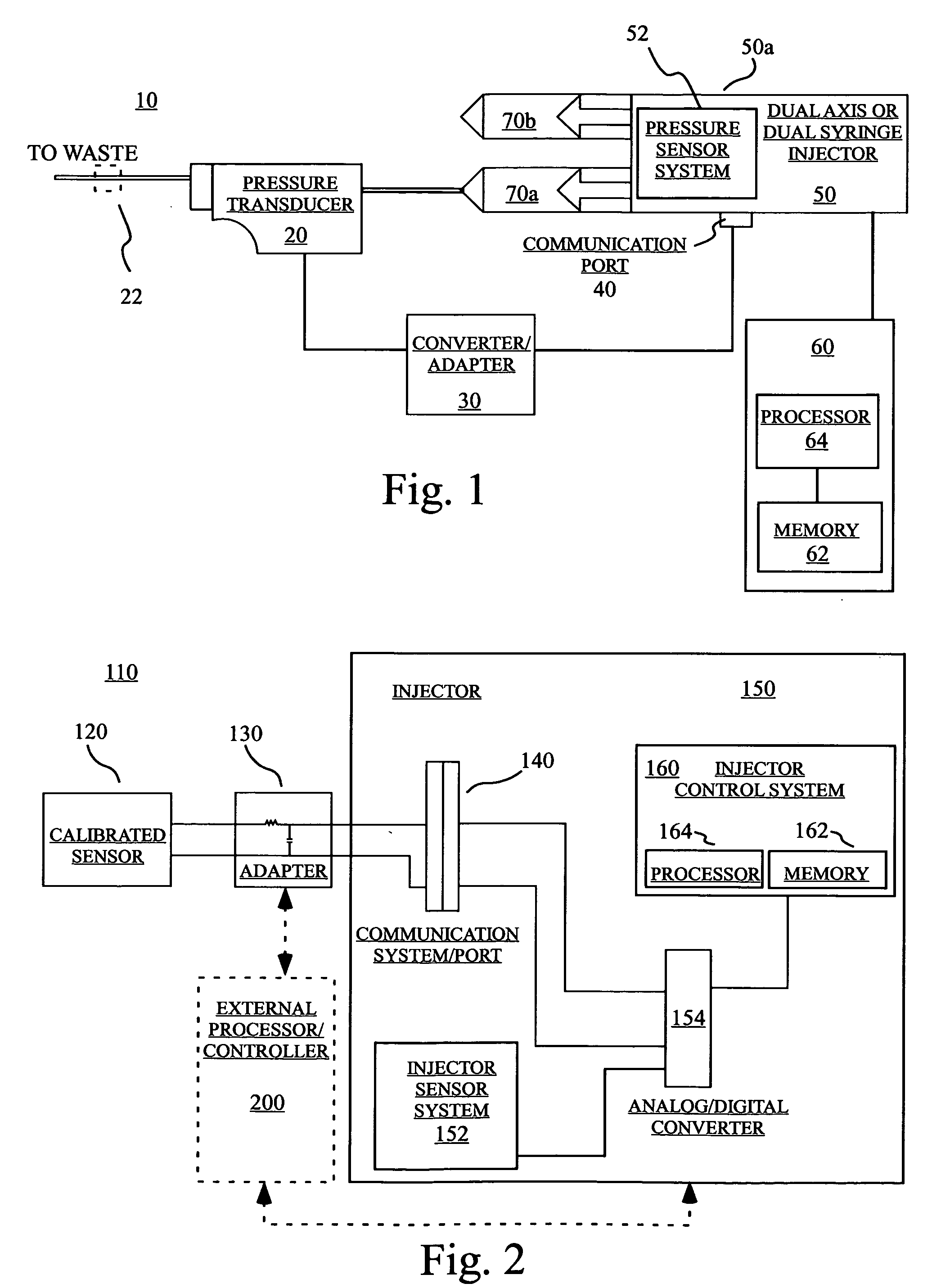
[0022] Several representative embodiments of the present invention are discussed in connection with the retrofitting of a STELLANT® Injector available from Medrad, Inc. of Indianola, Pa. for use with the calibration devices, systems and method of the present invention to calibrate one or more pressure measuring systems of the injector. However, one skilled in the art appreciates that the calibration devices, systems and methods are suitable for use in generally any injector system or in any other system to calibrate generally any measured variable.

[0023] In general, the pressure calibration devices, systems and methods of the present invention enable pressure calibration of an injector to be automatically performed by the injector with no (or minimal) user / manual interaction. In several embodiments of pressure calibration, this result is accomplished by communicating to the injector the output of a pressure transducer mounted on or placed in fluid connection with the tip of a syrin...


PUM


Abstract

An injector system for use in injecting a fluid into a patient includes a communication system adapted to receive data from at least a first sensor that measures a value first variable. The communication system is also adapted to receive data from a calibrated sensor that measures a value the first variable. The injector system further includes a calibration system adapted to calibrate output from the first sensor in response to output from the calibrated sensor. An injector for use in injecting a fluid into a patient, includes a first sensor that measures a value first variable, a communication port adapted to receive data from a calibrated sensor that measures the value the first variable, and a controller adapted to compare data from the calibrated sensor with data from the first sensor and to calibrate output from the first sensor. The devices, systems and methods of the present invention are applicable to systems other than injection systems. For example, a method for calibrating a system (for example, an injector system) includes: placing a calibrated sensor in communication with the system; making a measurement of the value of at least a first variable with the calibrated sensor; transmitting the measured value from the calibrated sensor to the system via a data communication system in operative connection between the calibrated sensor and the system; making a measurement of the value of the first variable with a sensor of the system at approximately the same time as the measurement made with the calibrated sensor; comparing the value of the first variable measured with the calibrated sensor with the value of the first variable measured with the system sensor; and calibrating the output of the system sensor at least in part based upon the comparison.

Description

CROSS-REFERENCE TO RELATED APPLICATION [0001] This application claims benefit of U.S. Provisional Patent Application Ser. No. 60 / 665,687, filed Mar. 28, 2005, the disclosure of which is incorporated herein by reference.BACKGROUND OF THE INVENTION [0002] The present invention relates generally to devices, systems and methods for calibration of systems such as injectors and, particularly, to devices, system and methods for pressure calibration of injectors used to inject fluid into a patient (either a human or a so-called lower animal). [0003] In many medical diagnostic and therapeutic procedures, a physician or other person injects a patient with a fluid. Over the past several decades, a number of injector-actuated syringes and powered injectors for pressurized injection of fluids such as contrast media have been developed for use in procedures such as angiography, computed tomography, ultrasound and NMR / MRI. In many applications, these powered injectors are designed to deliver a pre...

Claims


Application Information

Patent Timeline
Patent Type & Authority Applications(United States)
IPC IPC(8): G01F25/00A61M5/172A61M5/48
CPCA61M5/007A61M5/1452A61M2205/3344A61M2205/702G01F25/003G01F25/13
Inventor URAM, MARTIN J.FRAZIER, MICHAEL G.ADAMS, KENTON E.
Owner MEDRAD INC.
Learn More