
Multiprocessor system

a multi-processor and processor technology, applied in the field of multi-processor systems, can solve the problems of difficult analysis of faults, inability to store fault information in shared memory, and difficulty in analyzing cooperative or interrelated operations of all processors, and achieve the effect of reliable collection of running history information

Inactive Publication Date: 2006-09-21
FUJITSU LTD
View PDF34 Cites 8 Cited by
  • Summary
  • Abstract
  • Description
  • Claims
  • Application Information

AI Technical Summary

Benefits of technology

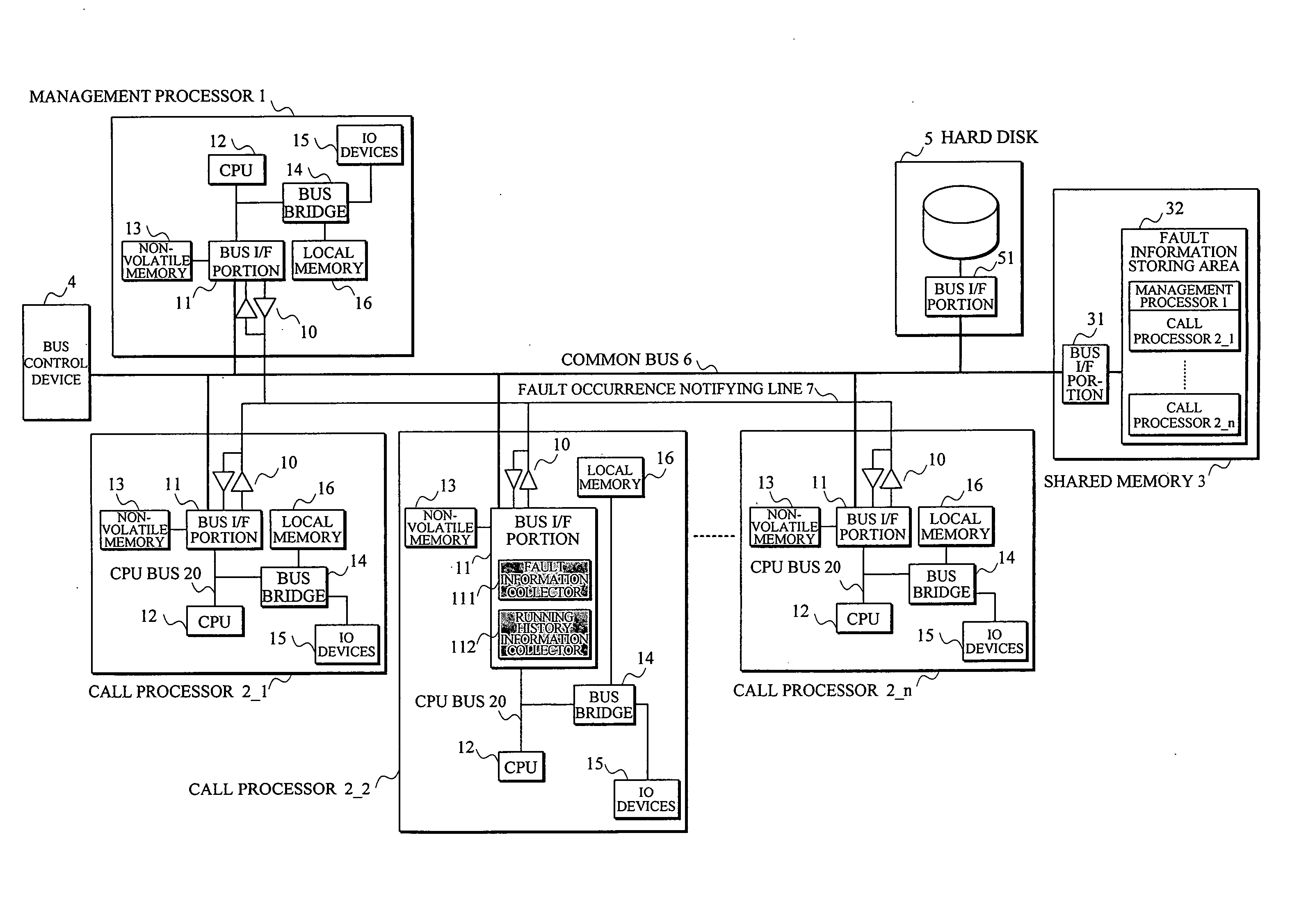
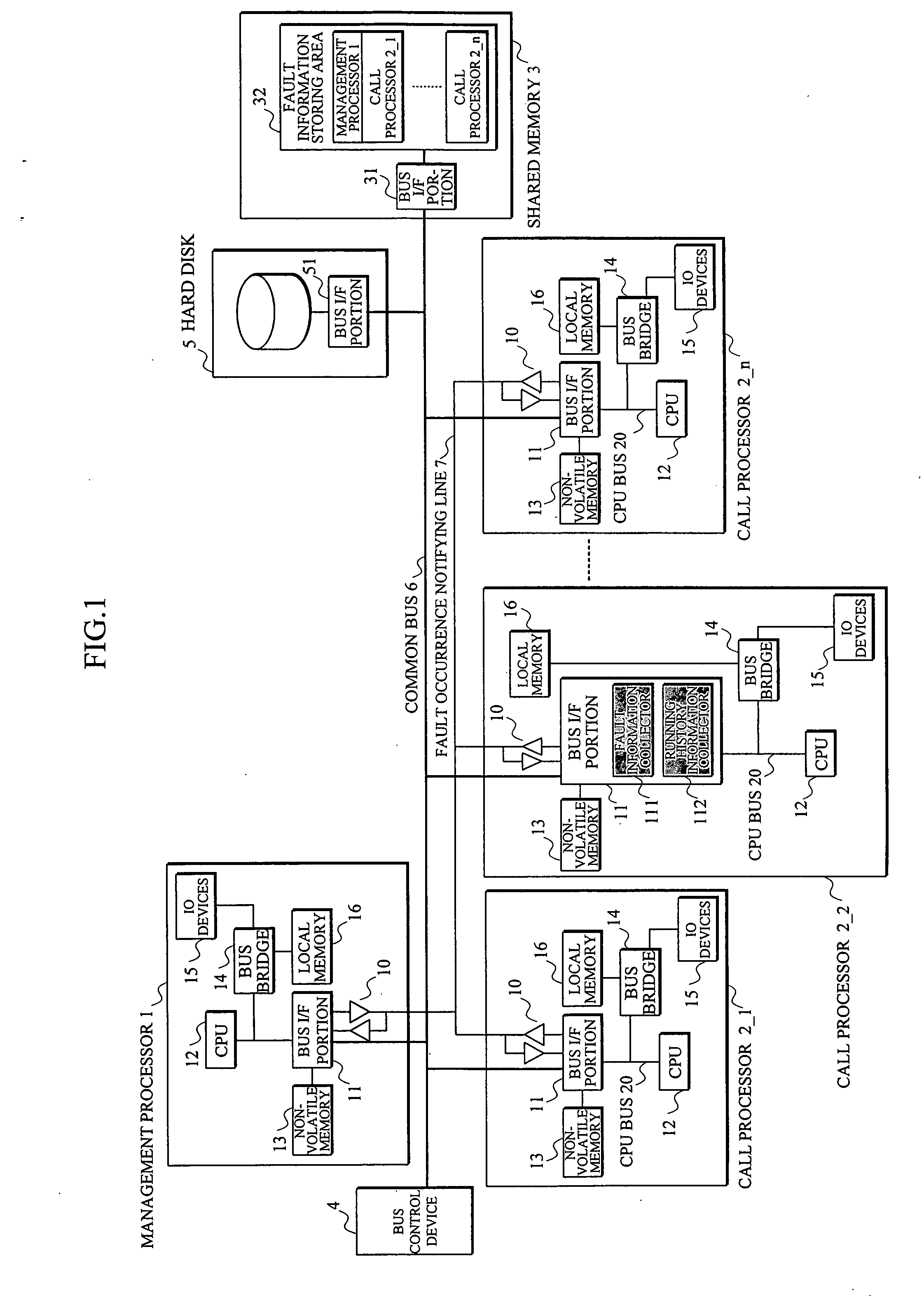
[0035] When a system power is turned on or a system is started up at a system restart or the like, in the multiprocessor system according to the present invention, a management processor 1 firstly provides, to all of processors 2, synchronized time information common to each of the processors. In each of the processors 2, the running history information collector 112 constantly collects (traces) running history information on a CPU bus 20 associated with the time information, thereby enabling the collection of information before a fault occurrence.
[0047] (4) Even if running of the software is disabled, it becomes possible to reliably collect the fault information and to take out the collected information data, which further increases patterns of the fault data which can be analyzed.

Problems solved by technology

A fault information collection method which monitors a fault occurrence state by composing a sequence by the software of the management processor like a shared memory-type multiprocessor shown in FIG. 7 has problems as follows: (1) Since the call processor except the call processor having detected a fault collects no information (fault information) of 10 devices at the time of the fault occurrence, it is difficult to analyze a cooperative or interrelated operation of all of the processors.
(2) Since the fault information is collected with a fault detection as a trigger, information before the fault occurrence can not be obtained, so that it becomes difficult to analyze the fault.
(3) Since the collected fault information is stored in the shared memory through the common bus, the fault information can not be stored in the shared memory when a fault has occurred in the common bus.
(5) Since the fault information is collected by the software, the software does not start up due to a runaway of the software, or credibility of the collected fault information becomes low.

Method used


Image

  • Multiprocessor system
  • Multiprocessor system
  • Multiprocessor system

Examples


Embodiment Construction

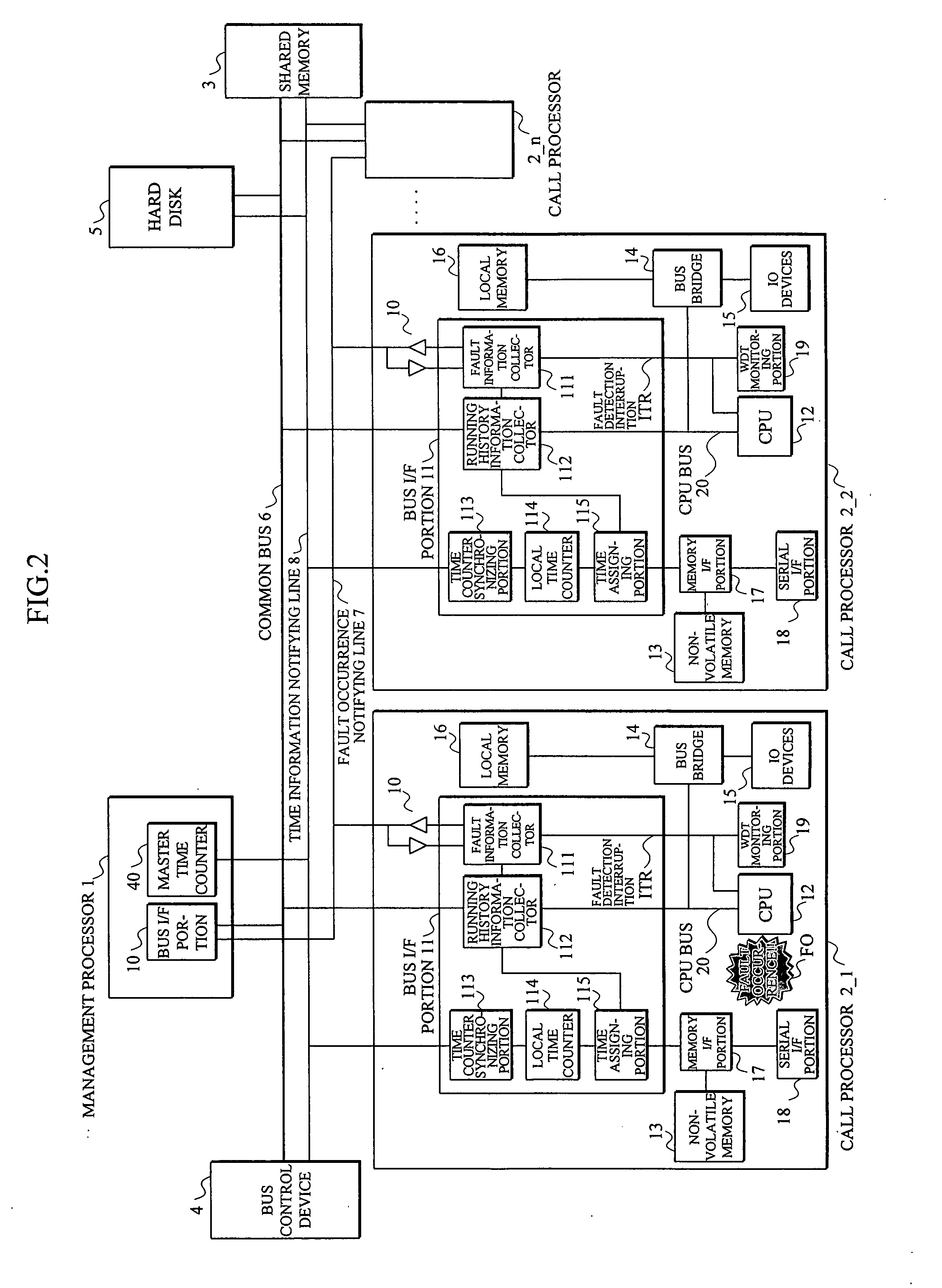
[0058]FIG. 2 specifically shows the multiprocessor system according to the present invention schematically shown in FIG. 1, and shows an embodiment in a case where the multiprocessor system is applied to the call processing device within the mobile communication system in the same way as FIG. 1.

[0059] In this embodiment, a multi-connection between the management processor 1, the call processors 2_1-2_n, the shared memory 3, the bus control device 4 and the hard disk 5 is performed with the common bus 6 and the time information notifying line 8, and a multi-connection between the processors 1 and 2 is performed with the fault occurrence notifying line 7.

[0060] Also, the management processor 1 is provided with a master time counter 40. Within the bus I / F portion 11, each of the call processors 2 has, as shown in FIG. 1, the fault information collector 111 connected to the fault occurrence notifying line 7 through a bidirectional driver 10, the running history information collector 1...


PUM


Abstract

In a multiprocessor system in which a plurality of processors are managed by a management processor, and an access to a shared memory is controlled by a bus control device, the management processor or the bus control device provides to the processors time information synchronized at a time of a system start-up, and each of the processors collects its own running history information associated with the time information. Also, when detecting a fault, each of the processors stops a collection of its own running history information, and stops a collection of running history information of other processors by notifying the fault detection to the other processors. Each of the processors, after having stopped the collection of its own running history information, stores the running history information in a nonvolatile memory provided other than the shared memory.

Description

BACKGROUND OF THE INVENTION [0001] 1. Field of the Invention [0002] The present invention relates to a multiprocessor system, and in particular to a multiprocessor system in which a plurality of call processors provided within a wireless network control device of a mobile communication system are managed by a management processor. [0003] 2. Description of the Related Art [0004] In call processing of a present mobile communication system, it is required to follow traffic rapidly increased together with an expansion of mobile telephone services as well as a spread of enormous data communication of voice, image and the like in a wireless network, so that the call processing is performed by an arrangement as shown in FIG. 6. [0005] In FIG. 6, a wireless network control device 103 controls base stations 102_1-102_3 (occasionally represented by a reference numeral “102”) transmitting / receiving information to / from a mobile unit 101, an outgoing / incoming call connection and the like, and pe...

Claims


Application Information

Patent Timeline
Patent Type & Authority Applications(United States)
IPC IPC(8): G06F11/00
CPCG06F11/0724G06F11/0778G06F11/0784G06F11/3476
Inventor YAMAGUCHI, KUNIOKAWASAKI, NAOKINOYAMA, MITSUHIROKAWAMOTO, MASATSUGU
Owner FUJITSU LTD
Learn More