Low Power array multiplier
a low-power array and multiplier technology, applied in the field of array multipliers, can solve the problems of low power consumption, and achieve the effects of reducing power consumption, reducing latency, and reducing power consumption
- Summary
- Abstract
- Description
- Claims
- Application Information
AI Technical Summary
Benefits of technology
Problems solved by technology
Method used
Image
Examples
first embodiment
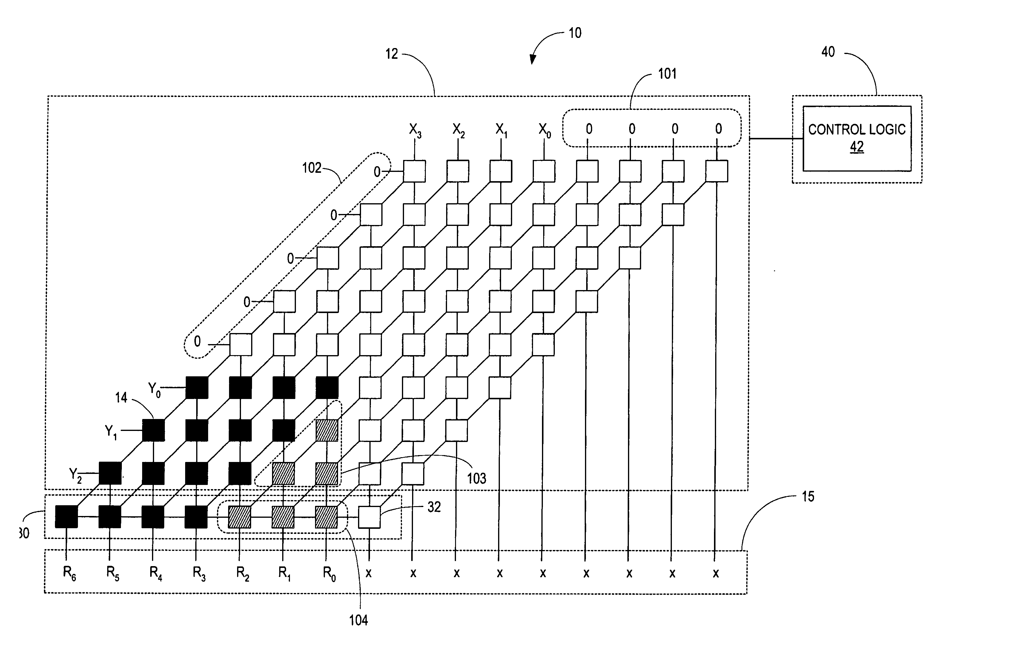
[0037]FIG. 4 illustrates one exemplary method for reducing power dissipated by the array multiplier 10 when the length of one or both operands is less than the maximum length of the partial product array 12. FIG. 4 illustrates multiplication of a 4-bit multiplicand by a 3-bit multiplier using an 8×8 array multiplier 10. As shown in FIG. 4, both the multiplicand and multiplier are input to the partial product array 12 in a shifted position. That is, the operands are shifted towards the most significant column or row of the partial product array 12. In the embodiment shown in FIG. 4, the operands are shifted to align the most significant bit of the operands with the most significant column and row respectively of the partial product array 12. Shifting the operands towards the most significant bit position of the partial product array 12 reduces the number of array elements 14 needed to compute the product of the operands. The array elements 14 and adder elements 32 needed for the comp...
second embodiment
[0042]FIGS. 5-7 illustrate a second exemplary embodiment of the array multiplier 10. The second embodiment is similar to the first embodiment shown in FIGS. 2-4. Therefore, for the sake of brevity and clarity, the same reference numerals will be used to designate similar components in the two embodiments and the discussion below will focus on aspects where the second embodiment differs from the first.
[0043] The array multiplier 10 according to the second embodiment comprises a partial product array 12 including a plurality of array elements 14 arranged in columns and rows, a carry propagate adder 30 including a linear array of adder elements 32, and a control circuit 40. The array elements 14 in the partial product array 12 and the adder elements 32 in the carry propagate adder 30 are interconnected as previously described with the following differences. In the second embodiment of the array multiplier 10, the partial product array 12 includes bypass lines 22 connecting array eleme...
third embodiment
[0048] The array multiplier 10 shown in FIGS. 5-7 allows operands to be shifted with one-bit granularity. The one-bit granularity allows operands of any size to be shifted completely to align the most significant bits of the operands with the most significant column and row respectively of the partial product array. The bypass lines 22, however, may introduce parasitic capacitance into the partial product array 12. Therefore, it may not be desirable to reduce the number and length of the bypass lines 22.
[0049]FIG. 8 illustrates another embodiment of the array multiplier 10 that uses fewer bypass lines 22 and thus reduces parasitic capacitance, but which has a coarser granularity. Array multiplier 10 comprises a partial product array 12 including a plurality of array elements 14, a carry propagate adder 30 including a linear array of adder elements 32, and a control circuit 40 as previously described. The control circuit 40 includes control logic 42 and control register 44 that oper...
PUM
 Abstract
Description
Claims
Application Information
 - R&D
- Intellectual Property
- Life Sciences
- Materials
- Tech Scout
- Unparalleled Data Quality
- Higher Quality Content
- 60% Fewer Hallucinations
Browse by: Latest US Patents, China's latest patents, Technical Efficacy Thesaurus, Application Domain, Technology Topic, Popular Technical Reports.
© 2025 PatSnap. All rights reserved.Legal|Privacy policy|Modern Slavery Act Transparency Statement|Sitemap|About US| Contact US: help@patsnap.com


