Removal and repositioning device

Inactive Publication Date: 2006-09-21
GI DYNAMICS
View PDF99 Cites 112 Cited by
  • Summary
  • Abstract
  • Description
  • Claims
  • Application Information

AI Technical Summary

Benefits of technology

[0006] The device also includes a retrieval hood. The retrieval hood is adapted to capture at least a portion of the implantable device. For example, the retrieval hood may be advanced over a proximal portion of the device in order to facilitate removal or repositioning of the object. This is particularly advantageous when the device includes protrusions, such as barbs that might otherwise damage tissue of the natural bodily lumen. In some instances, the retrieval hood may be made of hard plastic that is transparent. The transparent retrieval hood may be advantageous to the repositioning procedure. For example, if the repositioning device is used through the working channel of an endoscope, the endoscope facilitates viewing and the transparency of the retrieval hood increases the field of view. Preferably, the retrieval hood is flared to facilitate fully capturing a large anchor or stent within the hood. The retrieval hood may also be composed of flexible material, such as plastic, to minimize damage to surrounding tissue as it is introduced into the body. In some instances, the retrieval hood may include an interior ramp. The interior ramp may facilitate centering of the grasper and the inner tube within the interior of the implantable device when radially collapsing the implantable device. Alternatively, or in addition, the interior ramp may facilitate centering of the collapsed implantable device within the flared retrieval hood when the retrieval hood is advanced over the collapsed implantable device.
[0007] The device also includes an outer tube. The outer tube also defines a lumen within which the inner tube is slidably engaged. The retrieval hood can be coupled to the distal end of the outer tube facilitating the acceptance of at least the proximal portion of the grasped implantable device.
[0008] In some embodiments, the elongated member can be a wire. The distal end of the elongated member may also be shaped to form the grasper. The elongated member is capable of slidable or rotational movement within the inner tube. In some instances, the proximal end of the elongated member may be coupled to an actuator, facilitating its movement within the inner tube.
[0010] In some embodiments, the grasper is coupled to a grasper locking mechanism. The grasper locking mechanism locks in place the elongated member coupled to the grasper when the grasper has pulled the drawstring of the implantable device and the implantable device has thus been radially collapsed. The grasper locking mechanism thus prevents inadvertent release of the collapsed implantable device.
[0011] In one embodiment, the repositioning device includes a retrieval locking mechanism. Once the retrieval hood is advanced distally to capture the collapsed implantable device, the inner tube with the elongated member disposed therein is secured with respect to the endoscope and therefore also the retrieval hood, thus preventing release of the collapsed implantable device with its collapsed barbs from the retrieval hood during the movement or removal. This minimizes the risk of damage to surrounding tissue.
[0012] In some embodiments, the repositioning procedure can be viewed and / or guided with a fluoroscope. A distal end of the inner tube may be marked with a radiopaque marker thus facilitating viewing and positioning of the inner tube with respect to the implantable device. Other features of the repositioning device and / or the implantable device may be marked with radiopaque markers thus facilitating the viewing and / or positioning of the features in order to sufficiently collapse the implantable device.

Problems solved by technology

Often, these gastrointestinal implants, due to the complex structure of the anchoring device, may not be removed without damaging surrounding tissue, unless by resection.

Method used


Image

  • Removal and repositioning device
  • Removal and repositioning device
  • Removal and repositioning device

Examples


Embodiment Construction

[0021] A description of preferred embodiments of the invention follows.

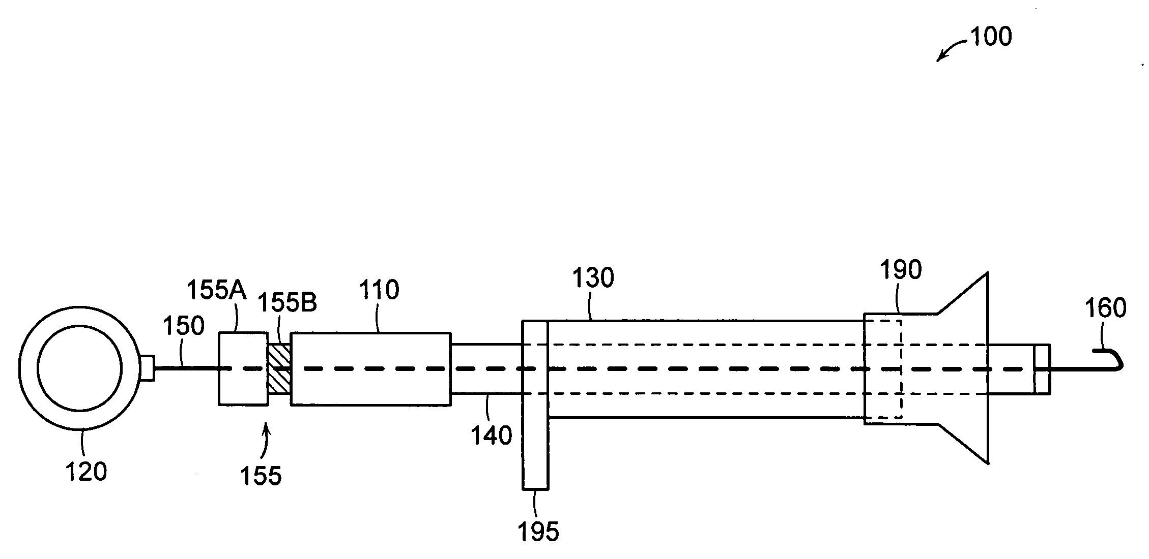
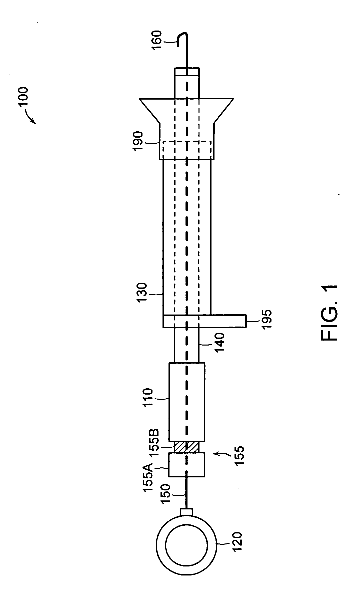
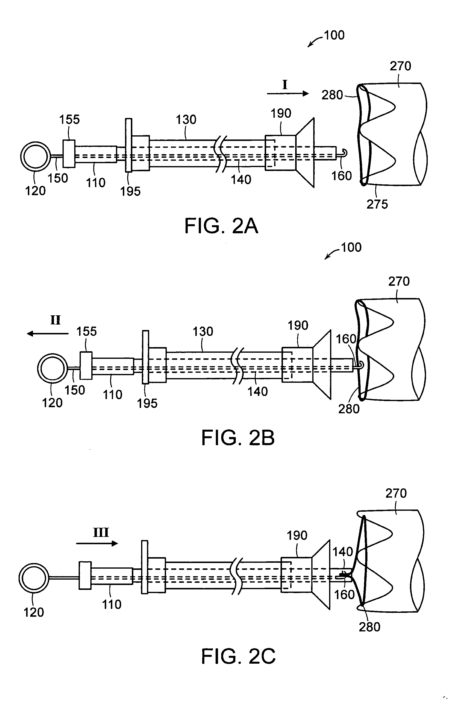
[0022] Gastrointestinal implants can be used for a number of treatments, at least some of which are described in U.S. patent application Ser. No. 10 / 339,786, filed on Jan. 9, 2003 and incorporated herein by reference in its entirety. Implants placed within the gastrointestinal tract are typically subject to substantial mechanical forces related to the digestion process. For example, an implant placed within the intestine, distal to the pyloric sphincter, will be subjected to peristaltic forces tending to push and pull the implant along the intestine. To keep the implant in place, an anchoring device is required. Anchoring can include conventional surgical techniques, such as sutures, staples, surgical adhesives, etc. Anchoring within the intestine, however, poses a unique set of challenges. At least some anchoring devices use an interference fit, placing an implant device having a relaxed diameter larger than th...


PUM


Abstract

A device for repositioning an implantable device within a natural bodily lumen includes an inner tube defining an internal lumen and adapted for insertion into a natural bodily lumen. An elongated member is slidably or rotatably disposed within the lumen of the inner tube, with a grasper disposed at the distal end of the elongated member adapted to grasp a portion of the implantable device. The implantable device, once grasped, can be at least partially collapsed. For example, a hook-shaped grasper grasps a drawstring of the implantable device, manipulating the drawstring and causing the implant to radially collapse. A retrieval hood is advanced over the collapsed portion of the implantable device. While maintaining its grasp, the repositioning device and the implantable device can then be repositioned or removed as one unit from the body by pulling the repositioning device from its proximal end.

Description

RELATED APPLICATION(S) [0001] This application claims the benefit of U.S. Provisional Application No. 60 / 663,352 filed Mar. 17, 2005. The entire teachings of the application are incorporated herein by reference.BACKGROUND OF THE INVENTION [0002] Gastrointestinal implants are used for a number of treatments such as stents to treat esophageal, pyloric or colonic obstruction, and gastrointestinal liners to treat obesity or diabetes. The implants placed within the gastrointestinal tract are normally subject to substantial mechanical forces related to the digestion process. For example, peristaltic forces may force the implant to move distally. To keep the implant in place, an anchoring device is needed. Anchoring can include conventional surgical techniques, such as sutures, staples, surgical adhesives, and others. At least some anchoring devices use an interference fit, placing an implant device having a relaxed diameter larger than the diameter offered by the intestine. Other anchorin...

Claims


Application Information

Patent Timeline
IPC IPC(8): A61F11/00
CPCA61B1/00089A61B1/018A61B17/221A61B2017/00296A61B2017/00336A61B2017/22035A61B2017/347A61F5/0089
Inventor LAMPORT, RONALD B.MELANSON, DAVID A.
Owner GI DYNAMICS
Why Eureka
Try Eureka