
Carton Feeder with Extended Carton Hold Down Member and Carton Guide

a technology of holding down member and carton guide, which is applied in the direction of paper/cardboard containers, packaging, container making machinery, etc., can solve the problems of unpredictability of carton edge flutter, packaging machine jamming or other malfunction, and achieves faster speeds and fewer misfeeds

Inactive Publication Date: 2006-09-21
MEADWESTVACO PACKAGING SYST LLC
View PDF13 Cites 2 Cited by
  • Summary
  • Abstract
  • Description
  • Claims
  • Application Information

AI Technical Summary

Benefits of technology

[0007] The various embodiments of the present invention overcome the shortcomings of the prior art by providing a rotary carton feeder with an improved carton hold down member, and a carton guide that prevent collapsed sleeve-type cartons from misfeeding. Advantageously, the carton hold down member and guide enable the machine to run at faster speeds with fewer misfeeds.
[0010] As the cartons are transported by a vacuum wheel and relayed from one vacuum wheel to another, one or more means for guiding the cartons prevent misfeeds by holding each carton in the proper position to be engaged by the next vacuum wheel or to be conveyed away from the carton feeder. Means for guiding the cartons also function to reduce or eliminate unwanted flutter and deformation that can occur as each carton is relayed from one vacuum wheel to another.
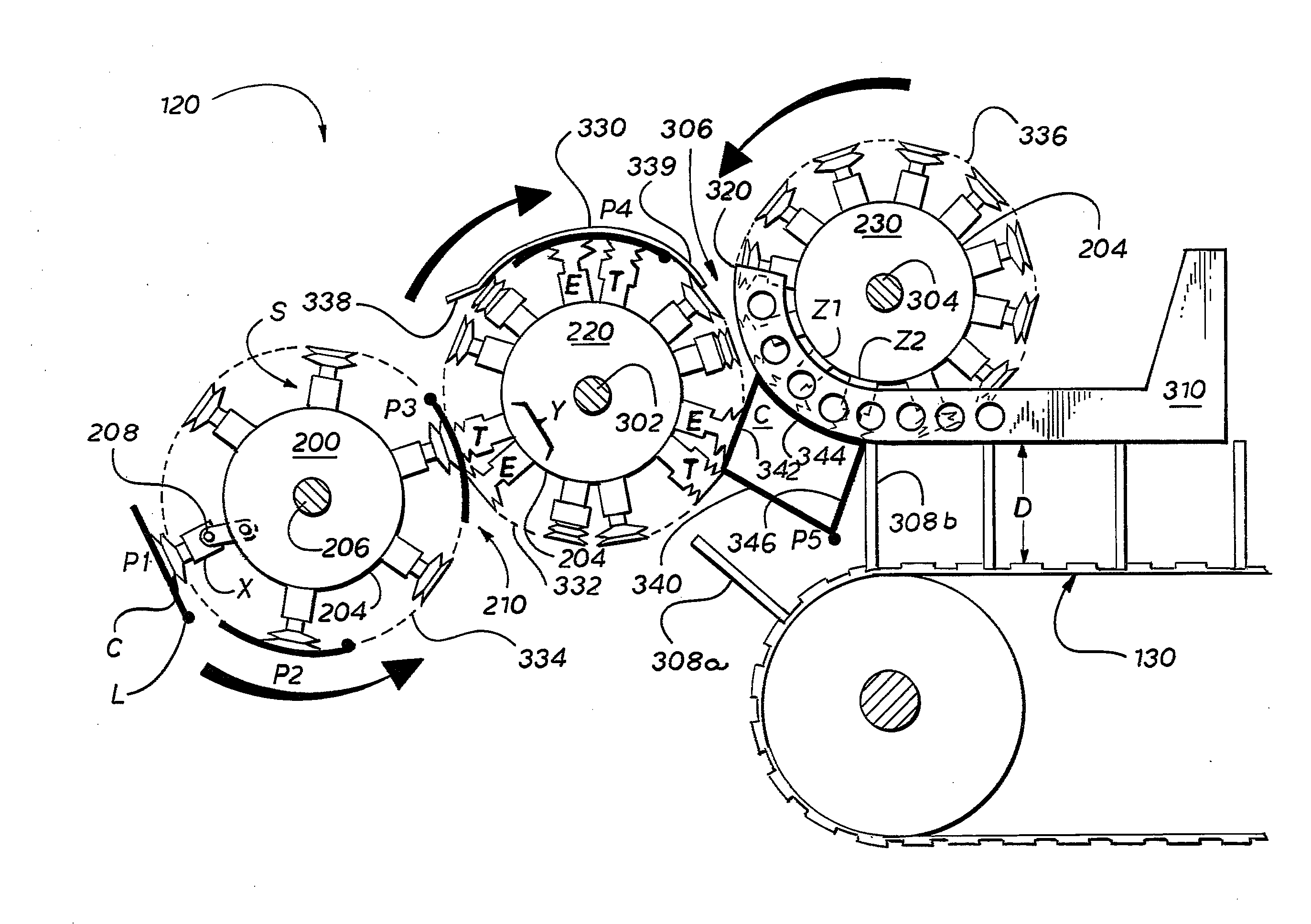
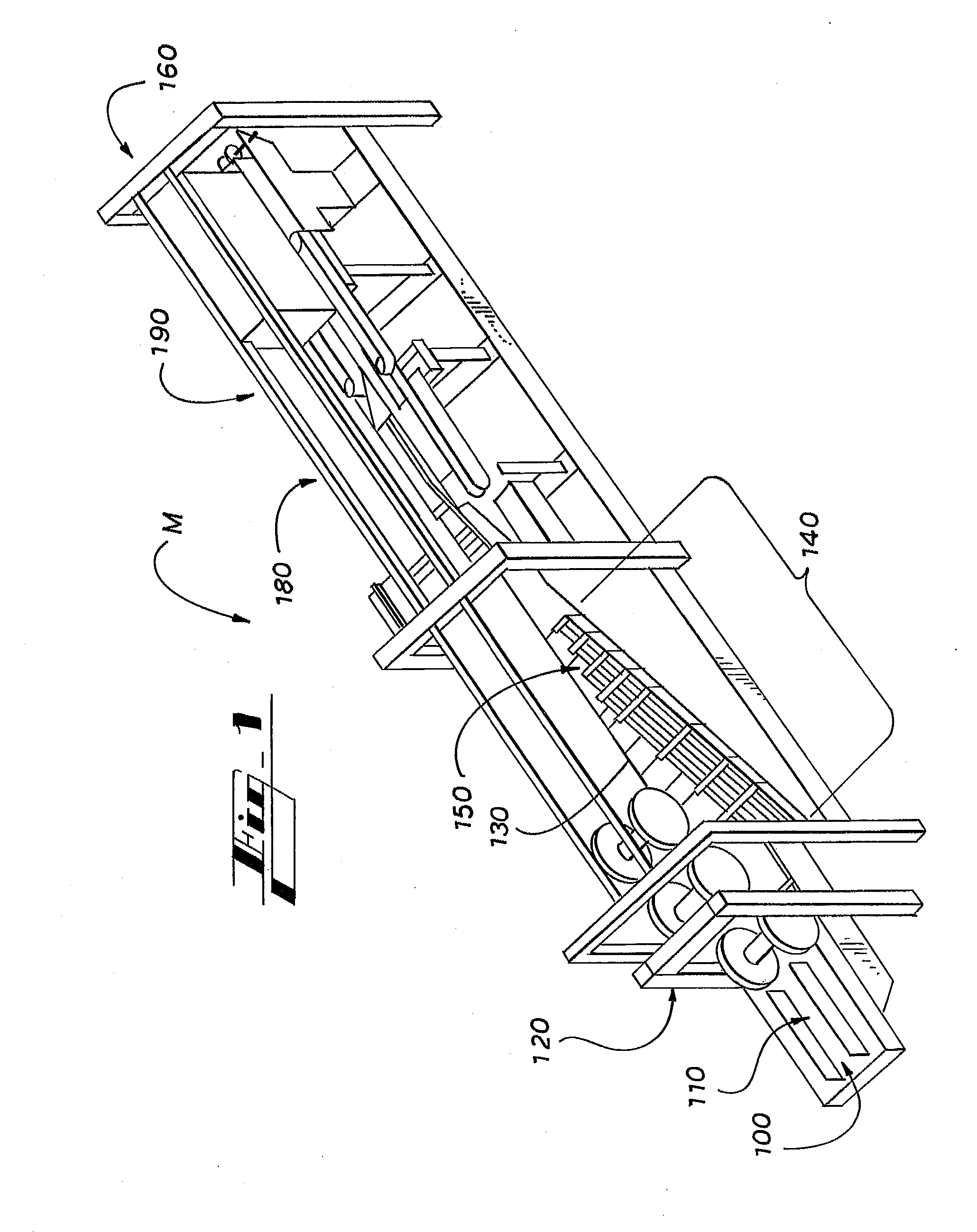
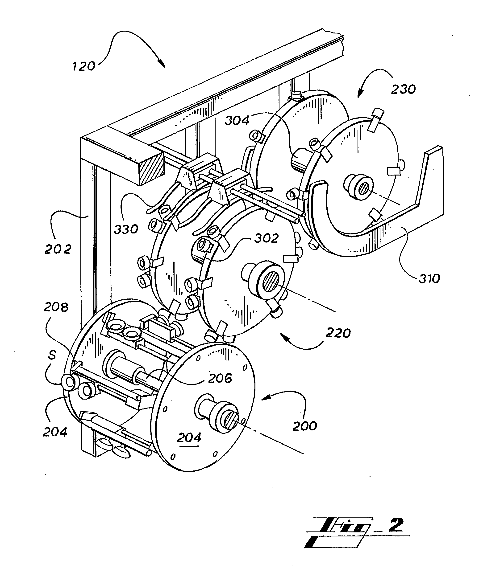
[0012] To relay the still collapsed carton from the pickup feeder to the transfer feeder, the transfer feeder engages a second face of the collapsed carton as the pickup feeder disengages a first face. According to one aspect of the invention, a guide, which is disposed above the transfer feeder, prevents the leading edge of the carton from extending substantially outside of the radial path of the engaging means that are attached to the transfer feeder. The transfer feeder relays the collapsed carton to the erecting feeder, which engages the first face of the collapsed carton before the transfer feeder disengages the second face of the collapsed carton. Because both the transfer feeder and the erecting feeder maintain concurrent and at least partial engagement with the collapsed carton, the faces of the carton are pulled apart. The engaging means are preferably aligned and the rotation of the feeders is preferably synchronized to ensure that panels on the opposing faces of the collapsed carton are simultaneously engaged by the two feeders, thereby at least partially erecting the carton. Before the now partially erected carton can spring back to a collapsed state, the erecting feeder deposits the partially erected carton on the carton conveyor between two adjacent lugs. A carton hold down member applies downward pressure to the partially erected carton. The lugs and the carton hold down member prevent the carton from collapsing as it is conveyed toward the loading station.
[0013] In one embodiment, means for guiding the cartons includes the aforementioned guide, at least a portion of which has a degree of curvature that is similar to that of the transfer feeder. The guide is fixed above the transfer feeder and is spaced at a distance that is just sufficient to allow the unhindered, although guided, passage of a collapsed carton therebetween. A first end of the guide preferably extends at least toward the first region of engagement. That is, the area at which the carton pickup feeder releases at least a portion of each carton and at which the transfer feeder engages at least a portion of the carton. The first end may flare outward somewhat with respect to the circumference of the transfer feeder in order to easily capture and guide the leading edge of the carton. A second end of the guide extends at least toward the second region of engagement. That is, the area between the transfer feeder and the erecting feeder. The second end of the guide serves to prevent the leading edge of the carton from missing engagement by the erecting feeder, which could potentially cause the carton to become lodged between suction cups or stations of the erecting feeder. The guide ensures that the carton is held at the optimal inflection for engagement.
[0014] In another embodiment, means for guiding the cartons includes an improved carton hold down member. A rear end portion of the carton hold down member has the same, or a substantially similar, degree of curvature as that of the erecting feeder. The curved portion of the carton hold down member extends at least to the second region of engagement, which is defined as the area at which the transfer feeder releases at least a portion of each carton and at which the erecting feeder engages at least a portion of the carton. This rear end portion is disposed alongside each of the end plates comprising the erecting feeder wheel. The rear end portion comprises two blades, each disposed along side each of the end plates comprising each the erecting feeder. The carton hold down member reduces the flutter that normally occurs when the leading edge of the carton is released by the transfer feeder. The leading edge of each carton can be released by the transfer feeder much sooner than with prior art carton feeders.
[0015] Other embodiments include both the guide and the carton hold down member, which cooperate to allow faster and more reliable operation. In these embodiments, the carton hold down member preferably extends vertically higher than the closest end of the guide.

Problems solved by technology

Frequently, misfeeds occur as the cartons are transitioned from one vacuum wheel to another.
In high speed packaging, when the leading edge of the carton is released by one vacuum wheel, the leading edge of the carton may flutter unpredictably.
This flutter of the leading edge results in an unacceptably high probability that the leading edge of the carton will become crumpled or inverted at a region of engagement with another vacuum wheel assembly, which causes the packaging machine to become jammed or otherwise malfunction.
Clearing the jammed packaging machine necessitates time-consuming and, therefore, costly intervention by a human or mechanical operator.
In this case, the packaging machine may expel bottles or other articles onto the conveyor where the carton should have been, which results in destruction of the articles, equipment malfunction, and again, costly intervention.

Method used


Image

  • Carton Feeder with Extended Carton Hold Down Member and Carton Guide
  • Carton Feeder with Extended Carton Hold Down Member and Carton Guide
  • Carton Feeder with Extended Carton Hold Down Member and Carton Guide

Examples


Embodiment Construction

[0023] As required, detailed embodiments of the present invention are disclosed herein. It will be understood that the disclosed embodiments are merely examples to illustrate aspects of the invention that may be embodied in various and alternative forms. The figures are not necessarily to scale, and some features may be exaggerated or minimized to show details of particular components. In other instances, well-known materials or methods have not been described in detail to avoid obscuring the present invention. For example, components of a packaging machine or carton feeder that are not relevant to the implementation of the invention may be omitted, obscured, scaled up or down, or depicted functionally rather than realistically. Therefore, specific structural and functional details disclosed herein are not to be interpreted as limiting, but as a basis for the claims and for teaching one skilled in the art to variously employ the present invention.

[0024] Referring now to the drawing...


PUM


Abstract

A packaging machine includes a carton feeder with rotary feeders that select, transport, and partially erect collapsed sleeve-type cartons in preparation for loading articles into each partially erected carton before its ends are sealed. A guide causes the collapsed carton to conform to the orbital path of a transfer feeder so as to optimize its presentation for engagement by an erecting feeder. An extended carton hold down member stabilizes the collapsed carton so as to enable the transfer and the erecting feeders to briefly engage the collapsed carton simultaneously, thereby partially erecting the carton, while preventing fluttering and jamming caused by premature release of the carton. The guide also prevents the extended carton hold down member from interfering with the passage of the collapsed carton. The rear portion of the carton hold down member provides stabilizing pressure to prevent the carton from collapsing before it is loaded.

Description

CROSS-REFERENCE TO RELATED APPLICATIONS [0001] This application claims priority to U.S. application Ser. No. 60 / 664,325, filed Mar. 21, 2005, the entirety of which is incorporated herein by reference.TECHNICAL FIELD [0002] This invention relates generally to machines for erecting sleeve type cartons or other packages, and more particularly, to a carton guiding system that facilitates high speed feeding of such cartons from a carton hopper. BACKGROUND OF THE INVENTION [0003] A continuous-motion automatic packaging machine rapidly applies secondary packaging to multiple individually packaged products, such as canned or bottled consumables, for greater ease of transportation, storage, sale, and consumer utilization. Many such packaging machines integrate several modular stations including carton erectors, case packers, carton sealing machines, palletisers, and interconnecting conveyor systems. The interconnecting conveyor systems convey the products through the other various modular st...

Claims


Application Information

Patent Timeline
Patent Type & Authority Applications(United States)
IPC IPC(8): B31B1/78B31B50/78
CPCB31B1/06B31B1/80B31B2201/027B31B2201/287B31B2201/289B31B2203/003B31B2203/084B31B50/00B31B50/80B31B2100/00B31B2120/30B31B50/062B31B50/804B31B2100/0024
Inventor FLAGG, MICHAEL F.PATTERSON, RAFE T.HACKWORTH, ROMAN S.
Owner MEADWESTVACO PACKAGING SYST LLC
Learn More