
Imaging device

a technology of imaging device and xenon lamp, which is applied in the field of imaging device, can solve the problems of forming a real risk for technicians replacing said lamps or working on imaging devices, xenon lamps, and high cost, and achieves the advantages of rugged imaging devices, high brightness, and not prone to explosion

Inactive Publication Date: 2006-09-21
BARCO NV
View PDF8 Cites 0 Cited by
  • Summary
  • Abstract
  • Description
  • Claims
  • Application Information

AI Technical Summary

Benefits of technology

The present invention is an imaging device that uses a direct current short arc metal halide lamp and at least one reflective light valve. The advantages of this design include a safer and easier to handle metal halide lamp, compact size, high brightness, and a stable light beam with a single and synchronized hotspot. The use of a direct current short arc metal halide lamp in an imaging device results in a relatively high brightness to power ratio and a relatively low cost of operation. The invention also includes the use of a direct current short arc metal halide lamp in an imaging device.

Problems solved by technology

A disadvantage of using said xenon lamps however is that they are highly vulnerable for explosion, thereby forming a real risk for technicians replacing said lamps or working on the imaging device.
Another disadvantage of said xenon lamps is that they are quite expensive compared to, for example said low pressure alternate current metal halide lamps.
A drawback of using alternate current metal halide lamps is that the emitted light fluctuates in function of the polarity of the current supply.
A disadvantage of said alternating hotspots that emit a very intense light, is that the control of the reflective light valve should be synchronized with the current alternations in order to build a stable image with a continuous brightness.
A disadvantage hereof is that only half of the emitted light is used for image building, what clearly is unfavorable for the brightness of the projected image and results in high operation costs.
Another disadvantage of an alternate current metal halide lamp is that such lamps are characterized by a relative long arc, which implicates that the light emitted by such metal halide lamp is spread over a relative big surface, thereby lowering the brightness of the emitted light.

Method used


Image

  • Imaging device
  • Imaging device

Examples


Embodiment Construction

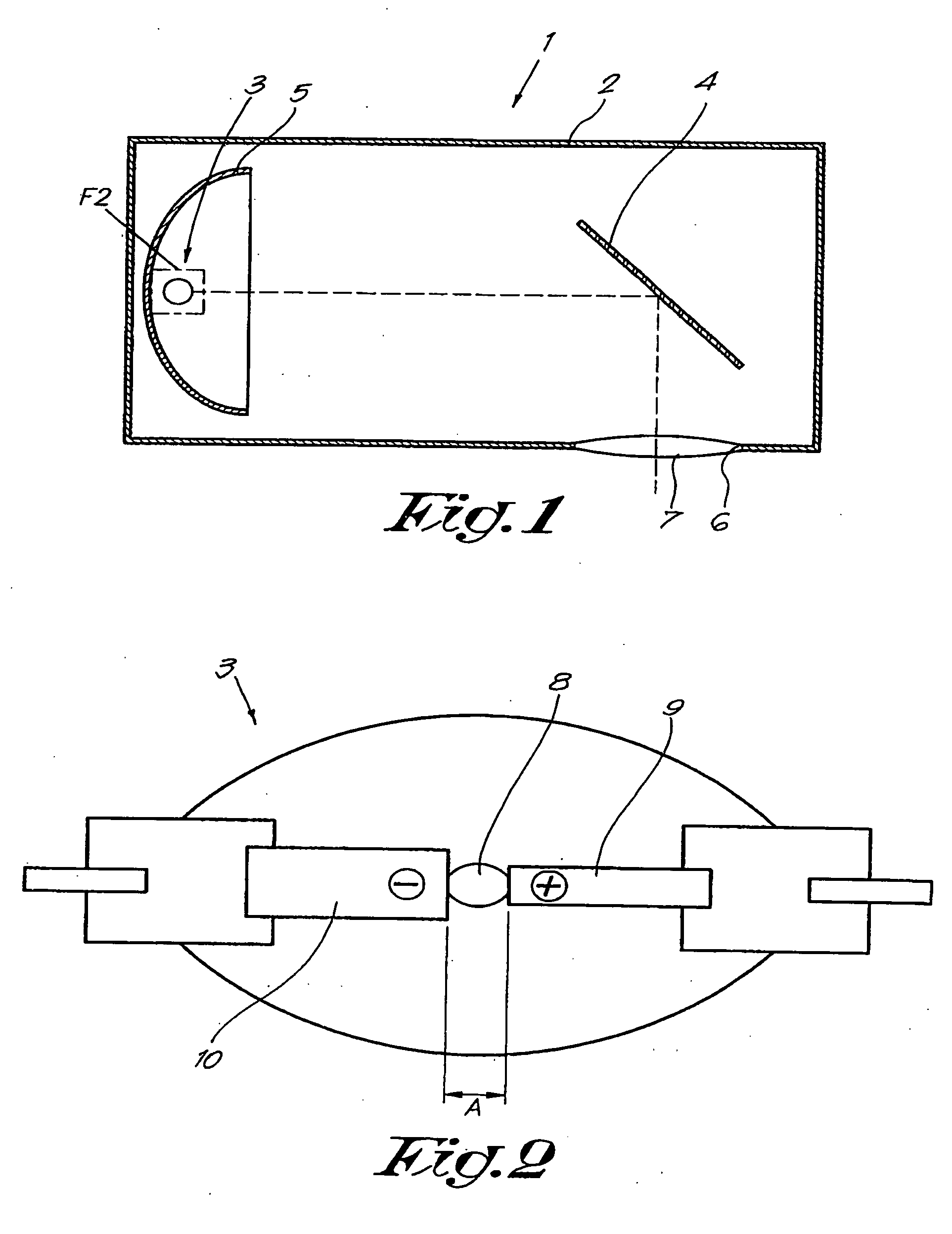
[0026]FIG. 1 represents an imaging device 1 according to the invention that mainly consists of a housing 2 wherein a light source 3 and a reflective light valve 4 are provided, whereby the light source is preferably provided with a reflector mirror 5.

[0027] The housing 2 contains a window 6 wherein or in front of which a lens 7 is provided.

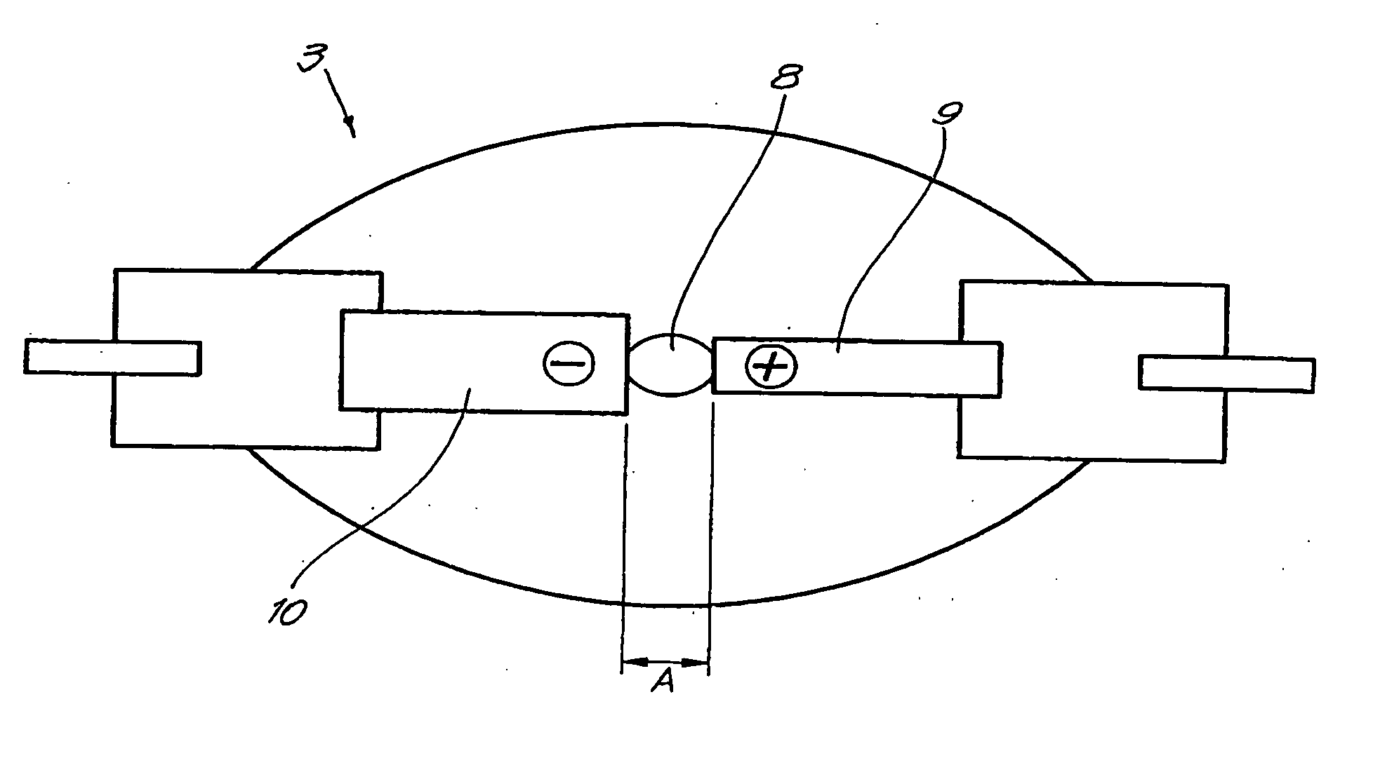
[0028] According to the invention, said light source 3 is a direct current short arc metal halide lamp, whereby the length A of the arc 8, as is represented in FIG. 2, can be defined as the distance between an anode 9 and a cathode 10 of the metal halide lamp. The term short arc should in this case be understood as an arc 8 having a length A that is less than 6 mm, and preferably even less than 3 mm.

[0029] It is remarked that said metal halide lamp is preferred to be a high power lamp with a wattage of at least 300 W.

[0030] Furthermore, the metal halide lamp is preferably a low pressure lamp, which is advantageous in that it is quite safe to m...


PUM


Abstract

An imaging device comprising a direct current short arc metal halide lamp and at least one reflective light valve.

Description

BACKGROUND OF THE INVENTION [0001] 1. Field of the Invention [0002] The present invention relates to an imaging device, more specifically to a lighting device or a projection device comprising a direct current metal halide lamp. [0003] 2. Discussion of the Related Art [0004] As known, an imaging device generally comprises a light source and a reflective light valve such as, for example, a digital micro mirror device (DMD). [0005] The currently applied light sources hereby are high pressure xenon lamps or low pressure alternate current metal halide lamps. [0006] A disadvantage of using said xenon lamps however is that they are highly vulnerable for explosion, thereby forming a real risk for technicians replacing said lamps or working on the imaging device. [0007] Another disadvantage of said xenon lamps is that they are quite expensive compared to, for example said low pressure alternate current metal halide lamps. [0008] A drawback of using alternate current metal halide lamps is th...

Claims


Application Information

Patent Timeline
Patent Type & Authority Applications(United States)
IPC IPC(8): G02B5/08G02B7/182
CPCH01J61/86H04N5/7458H04N9/315H04N9/3197
Inventor GERETS, PETER
Owner BARCO NV
Learn More