
Antenna

a broadband antenna and antenna element technology, applied in the field of broadband antennas, can solve the problems of high-cost antennas and low gain, and achieve the effects of wide band, favorable matching, and large surface area of antenna elements

Inactive Publication Date: 2006-09-21
SHINKO SANGYO CO LTD
View PDF0 Cites 5 Cited by
  • Summary
  • Abstract
  • Description
  • Claims
  • Application Information

AI Technical Summary

Benefits of technology

[0016] The main aspect of the present invention is composed of the antenna element formed in the substantially spherical shape, the conductive rod, and the conductive circular plate, and the feeding point is provided at a portion where the base end side of the conductive rod and the conductive circular plate intersect each other. The structure is provided such that the antenna element itself is spherically formed and the conductive rod is combined together so as to penetrate through this spherically formed antenna element, thus resulting in a larger surface area of the antenna element, no directivity provided on the horizontal plane, and an extremely broad band. Moreover, providing the conductive circular plate and configuring the antenna element to be slidable with respect to the conductive rod permits freely changing the distance from the conductive circular plate to the antenna element, thus permitting favorable matching. This fact has been already confirmed by experiments. Further, since the antenna element is formed in a spherical shape, forming the antenna element with a sphere permits a drastic reduction in the number of components used therein.
[0017] According to another aspect of the present invention, in the antenna including a reflecting plate formed in the parabolic shape and the primary radiator fitted to the focus of the reflecting plate, the primary radiator includes: the antenna element that is formed in the substantially spherical shape; the conductive rod that penetrates through the antenna element and that is electrically conducted to the antenna element; and the conductive circular plate that is disposed on the base end side of the conductive rod so as to be substantially orthogonal to the conductive rod, thereby permitting achieving a favorable antenna suited for high-speed transmission of digital data. Moreover, in the antenna including the dielectric lens and the primary radiator fitted to the focus of the dielectric lens, the primary radiator includes: the antenna element that is formed in the substantially spherical shape; the conductive rod that penetrates through the antenna element and that is electrically conducted to the antenna element; and the conductive circular plate that is disposed on the base end side of the conductive rod so as to be substantially orthogonal to the conductive rod, thereby permitting achieving a favorable antenna suited for high-speed transmission of digital data.

Problems solved by technology

This requires a larger number of components used therein and involves bothersome assembly, thus resulting in a high-cost antenna.
Moreover, this antenna has a drawback that the gain thereof is low due to a current generated by a radio wave that has been received by the plurality of curved plates.

Method used


Image

  • Antenna
  • Antenna
  • Antenna

Examples


Embodiment Construction

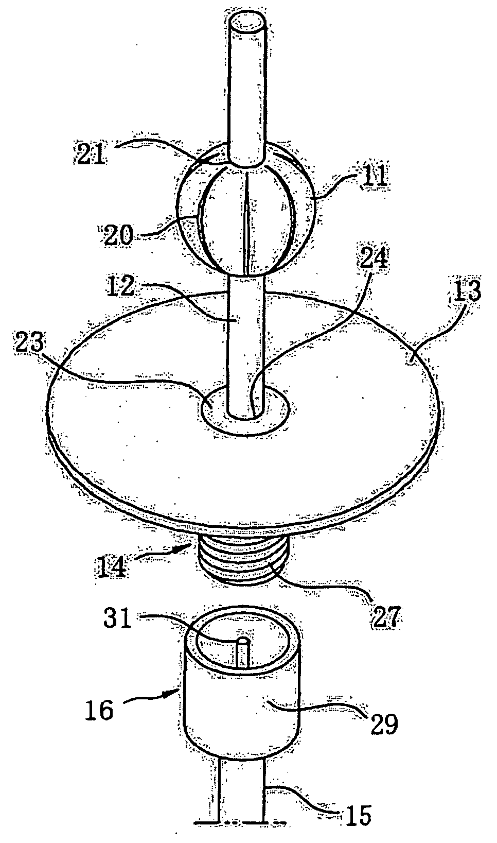
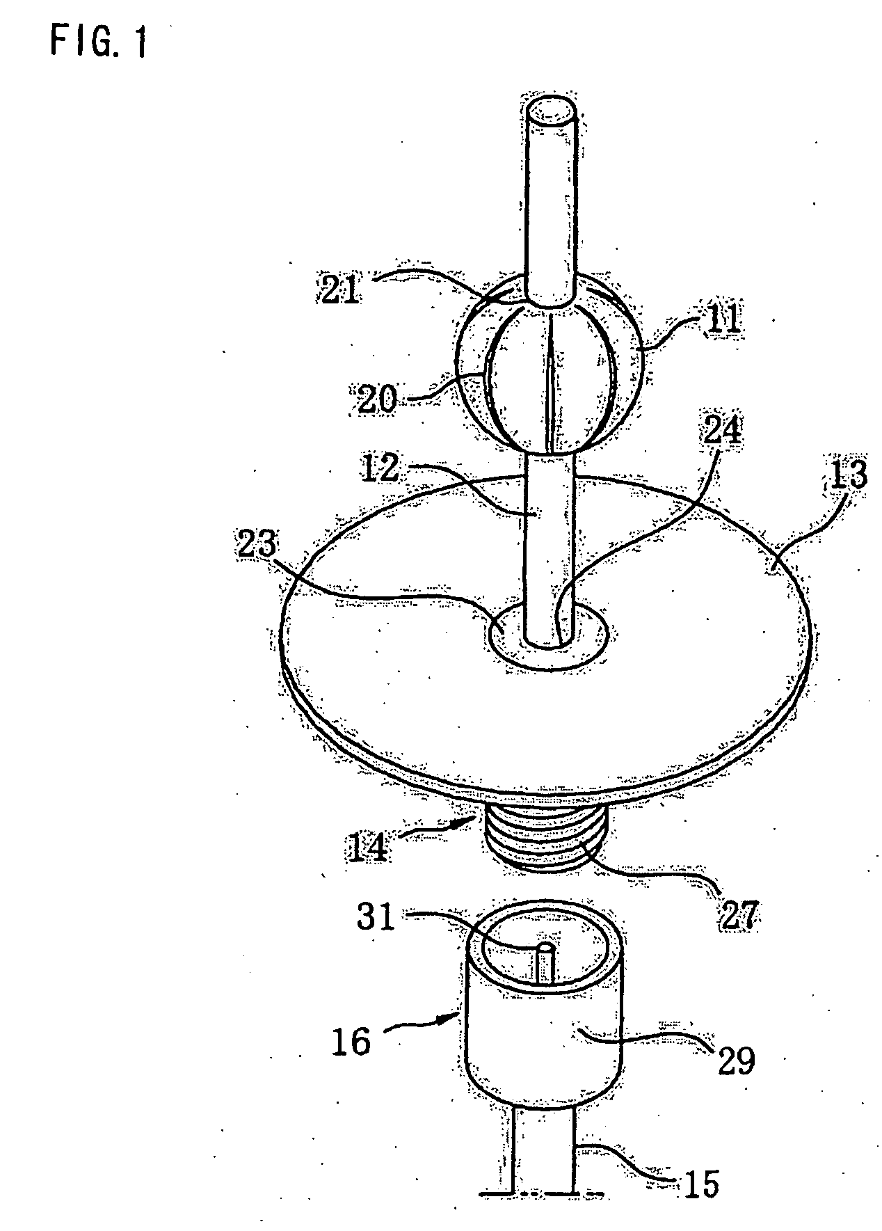
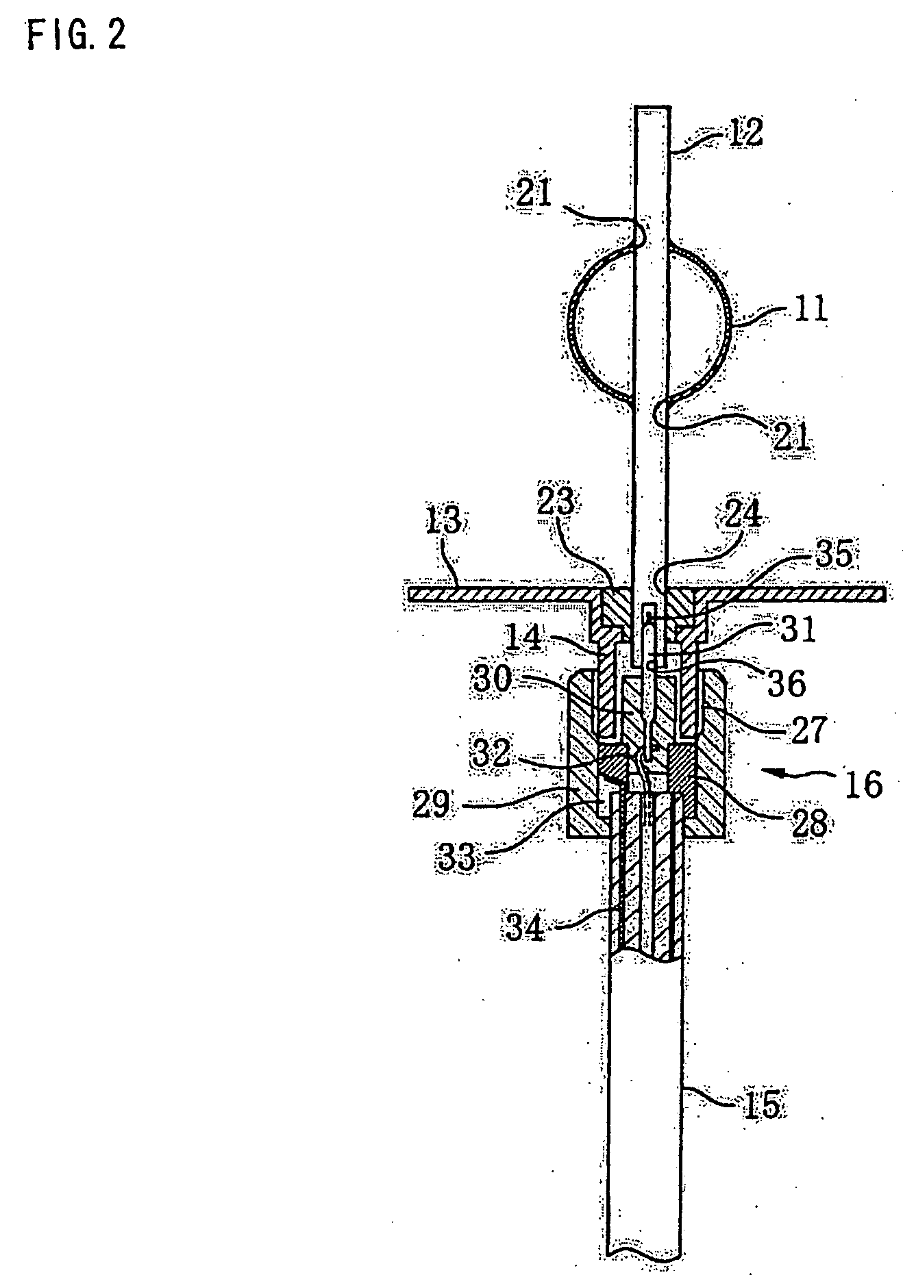
[0037]FIGS. 1 and 2 show the overall structure of the antenna according to one embodiment of the present invention. In the present embodiment, an antenna element 11 is used which is formed of a brass spherical shell having a diameter of 10 mm and a thickness of 0.2 mm. The antenna element 11 is provided on a rod 12 of brass having a diameter of, for example, 2.5 mm so that the rod 12 penetrates therethrough. The rod 12 is fitted on a conductive circular plate 13 of a brass discoid having a diameter of 30 mm so as to be provided upright. On the bottom surface of the conductive circular plate 13, a connector sleeve 14 is integrally linked. To this connector sleeve 14, a coaxial cable 15 is connected via a connector 16.

[0038] The antenna element 11 formed of the brass spherical shell has slits 20 having a width of 0.5 mm and formed on the outer circumferential surface thereof along the circumference thereof at intervals of 60 degrees. These slits 20 are formed in the vertical directio...


PUM


Abstract

A broadband antenna that is non-directional in the horizontal plane and that is capable of receiving a broadband radio wave, especially receiving a signal of a broad band extending over several Gigahertz. An antenna has a brass spherical shell having a diameter of, for example, 10 mm, fitted, in a skewered state, to a rod of brass having a diameter of 2.5 mm. This rod is held upright by an insulating bushing of nylon resin fitted at a central portion of a conductive circular plate. A coaxial cable is connected via a connector to a connector sleeve on the bottom surface of the conductive circular plate, with the rod connected to a core wire while the conductive circular plate is connected to a shield wire.

Description

TECHNICAL FIELD OF THE INVENTION [0001] The present invention relates to an antenna, and more specifically to a broad-band antenna that has no directivity on the horizontal plane. PRIOR ART [0002] The inventor of this application has proposed a non-directional antenna in Japanese Laid-Open Patent Publication No. H10-65425 (1998). This antenna is an antenna device having, on the outer circumferential side of a rod provided upright at a central portion thereof, a plurality of curved plates that are curved in the shape of a substantially circular arc so as to be convex toward the outer peripheral side in the radial direction. The plurality of curved plates, in particular, permits receiving radio waves from any direction, provides no directivity, and permits efficiently receiving radio waves from any direction. [0003] However, the structure is adopted in which this antenna is assembled so that the plurality of curved plates are arranged on the outer peripheral side of the rod. This requ...

Claims


Application Information

Patent Timeline
Patent Type & Authority Applications(United States)
IPC IPC(8): H01Q1/00H01Q5/00H01Q9/38H01Q9/40H01Q19/06H01Q19/13
CPCH01Q9/40H01Q19/02H01Q1/24H01Q9/24
Inventor SHIBATA, KAZUHIRO
Owner SHINKO SANGYO CO LTD
Learn More