Controller for brushless motor

a brushless motor and control board technology, applied in the direction of dynamo-electric converter control, ac motor direction control, dynamo-electric gear control, etc., can solve the problems of conspicuous noise and limited calculation period of current voltage applied to the coil, so as to reduce noise at the update frequency, reduce the effect of calculation load and reduce the nois

Active Publication Date: 2006-09-21
JTEKT CORP
View PDF5 Cites 6 Cited by
  • Summary
  • Abstract
  • Description
  • Claims
  • Application Information

AI Technical Summary

Benefits of technology

[0010] It is desirable that predicted values of the rotational position of the rotor are calculated by the rotational position calculating part at all points in time at which the applied voltages are updated until the next calculation of the present values of the applied voltages. As a result, the respective applied voltages at all points in time at which the applied voltages are updated can be caused to correspond to the rotational position of the rotor, so that the noise at the update frequency can be reduced even further.
[0011] It is desirable that the updating period of the applied voltage is set as a period that is shorter than the calculation period of the present values of the applied voltage so that the number of times that the applied voltages are updated in one calculation period of the present values of the applied voltages is three or more, that the predicted value of the rotational position of the rotor is calculated by the rotational position calculating part at any point in time at which the applied voltages are updated until the next calculation of the present values of the applied voltages, and that an interpolation calculating part is provided to determine the predicted values of the applied voltages to the coils at the remaining points in time at which the applied voltage are updated, by interpolation using the present values of the applied voltages and predicted values of the applied voltages calculated by the applied voltage calculating part. In order to reduce the noise at the update frequency of the applied voltages to the coils, it is desirable to increase the number of times that the updating is performed.
[0012] Compared to a case where all of the predicted values of the applied voltages to the coils are calculated from the d axis target current, q axis target current, d axis actual current, q axis actual current and predicted values of the rotational position of the rotor, a case where any predicted value of the rotational position and any predicted values of the applied voltages are calculated, and the remaining predicted values of the applied voltages are calculated from the present values and any predicted values of the applied voltages, results in a smaller calculation load. Accordingly, by reducing the number of times that calculations are performed by the applied voltage calculating part and rotational position calculating part and by increasing the number of times that calculations are performed by the interpolation calculating part, it is possible to prevent increase in the calculation load even if the number of times that the updating of the applied voltages to the coils is performed is increased.
[0013] It is desirable that the updating period of the applied voltage is set at 100 μsec or less. As a result, the noise that is caused by the updating of the applied voltages can be greatly reduced. It is even more desirable to set the updating period of the abovementioned applied voltages at 50 μsec or less. As a result, since the reciprocal (20 kHz) of the updating period of the applied voltages is enough greater than the maximum frequency (about 15 to 16 kHz) of the general audible range for humans, the abnormal noise caused by the updating of the applied voltages can be reduced even further.
[0014] It is desirable that the brushless motor is driven by PWM driving, that the updating of the applied voltages to the coils is performed by updating the duty ratio of the PWM control signals, and that the signal period of the PWM control signals is caused to correspond to the updating period of the applied voltages. As a result, the present invention can easily be realized with using PWM control.
[0015] The controller for brushless motor of the present invention makes it possible to suppress the generation of abnormal noise that occurs when the motor current is controlled by updating the applied voltages to the coils, and further makes it possible to suppress increase in the calculation load for that.

Problems solved by technology

However, the calculation period of the present values of the voltages applied to the coils is limited not only by the calculation time, but also by the rotational position of the rotor, the detection time required for the detection of the actual current and the like.
However, when the shortening of the calculation period for the present values of the applied voltages according to the rotational position of the rotor is limited, since the motor current varies in accordance with this calculation period, the following problem arises: namely, noise which has a noise peak in the vicinity of the frequency that is the reciprocal of this period is generated.
Furthermore, when the rotor rotates at a high speed, the current variation also increases with an increase in the voltage variation Δv at the time when the applied voltage is updated; accordingly, the noise becomes conspicuous.

Method used


Image

  • Controller for brushless motor
  • Controller for brushless motor
  • Controller for brushless motor

Examples


first embodiment

[0030] A controller for a brushless motor constituting the present invention is described with reference to FIGS. 1 through 8. In the present embodiment, parts that are the same as in the conventional example are labeled with the same symbols.

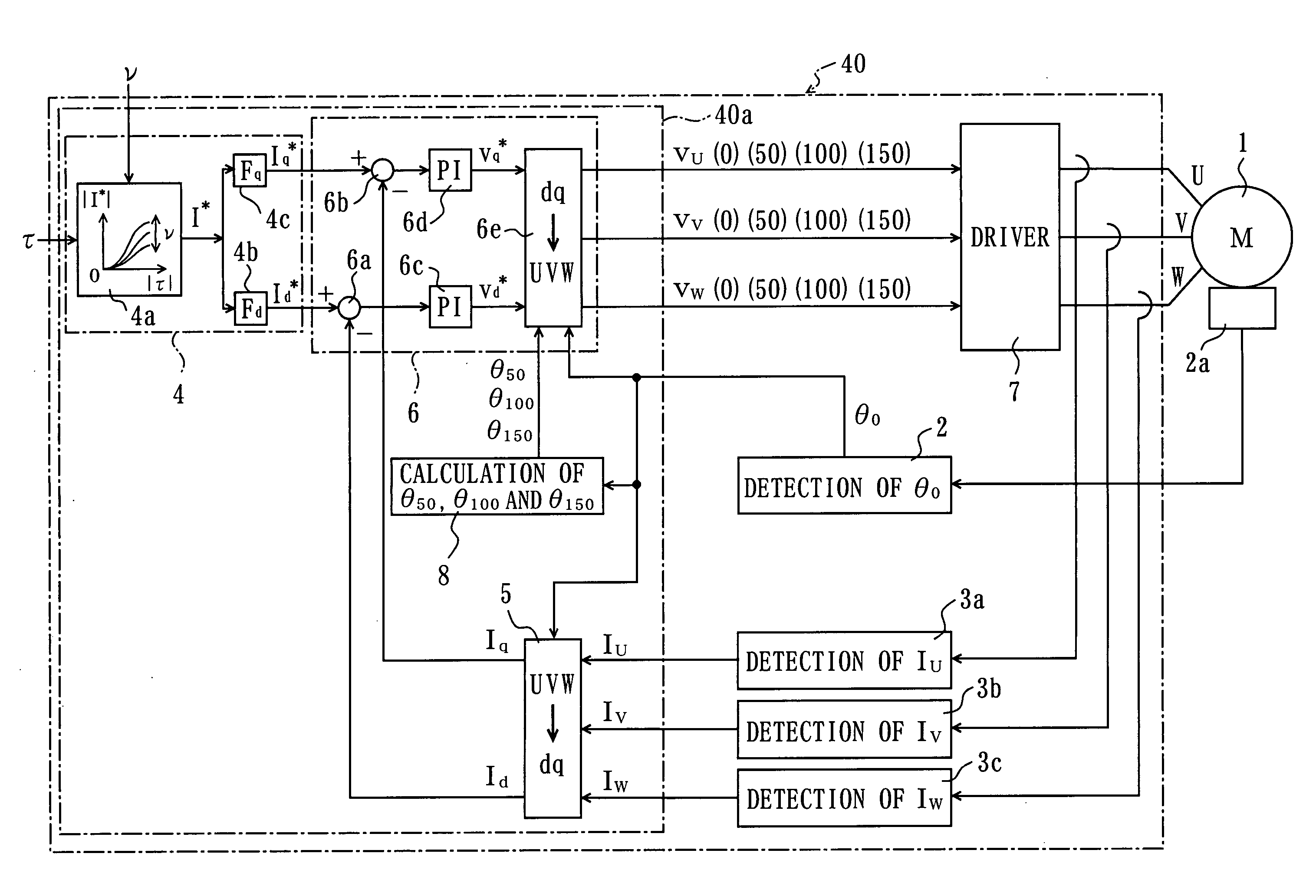
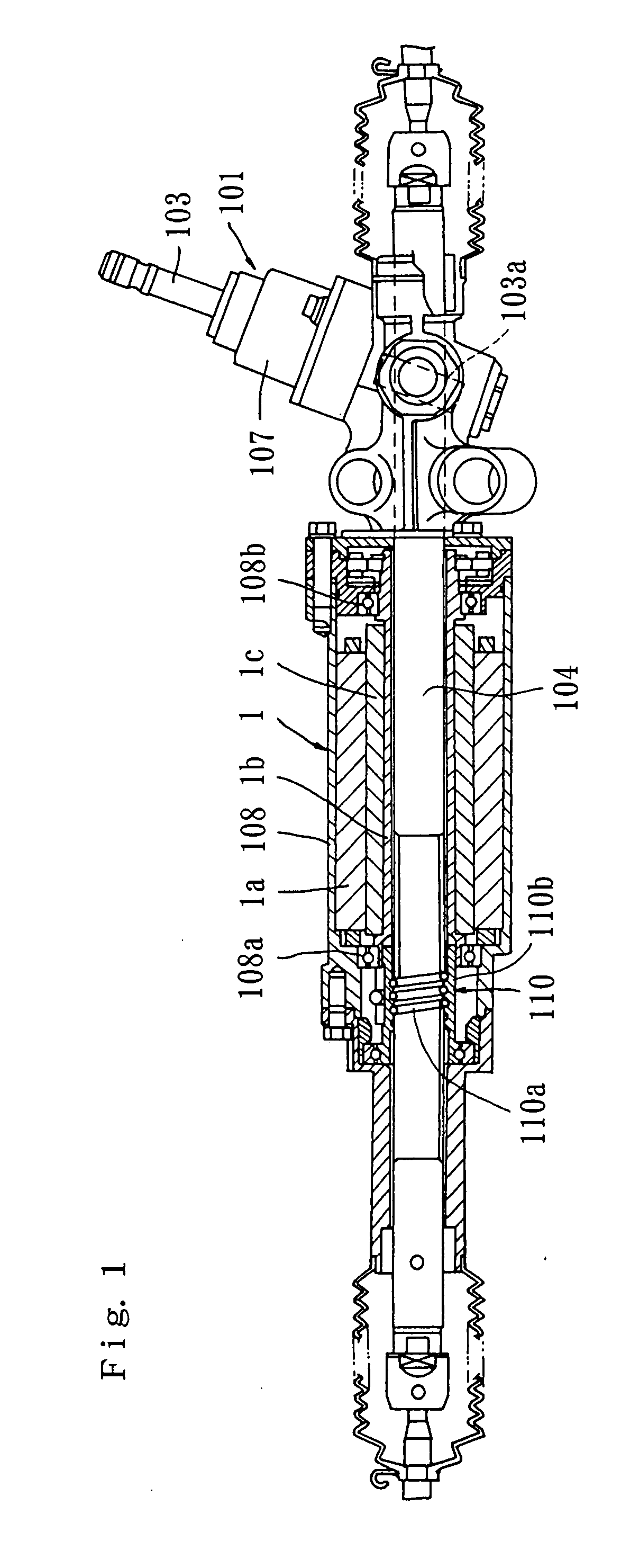
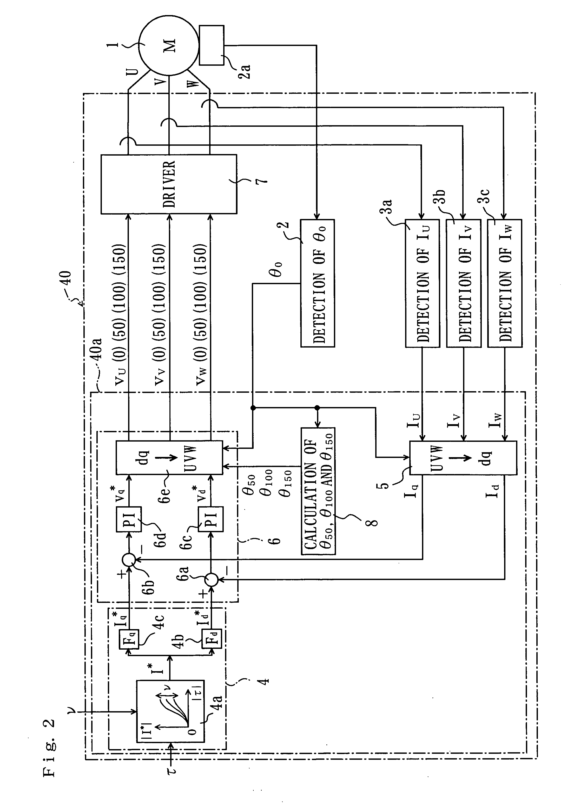
[0031] The rack and pinion type electrical power steering apparatus 101 for a vehicle shown in FIG. 1 comprises a steering shaft 103 that is caused to rotate by steering operation, a pinion 103a that is disposed on the steering shaft 103, and a rack 104 that engages with the pinion 103a. Both ends of the rack 104 are connected to vehicle wheels (not shown in the figures) used for steering. When the pinion 103a is caused to rotate by steering operation, the rack 104 moves in the longitudinal direction along the lateral direction of the vehicle, and the steering angle varies as a result of this movement of the rack 104. A torque sensor 107 which detects the steering torque, a three-phase brushless motor 1 which is driven in accordance with the de...


PUM


Abstract

In a controller for brushless motor which suppresses the generation of abnormal noise when the motor current is controlled by updating voltages applied to the coils, the present values of the applied voltages to the coils are calculated from the d axis target current, the q axis target current, the d axis actual current, the q axis actual current, and the present value of the detected rotational position of the rotor. The updating period of the applied voltages is set as a period that is shorter than this calculation period. The predicted value of the rotational position at a point in time at which the applied voltages are updated until the next calculation of the present values of the applied voltages is determined in accordance with the present value, a past value of the detected rotational position, and the applied voltage updating period. The predicted values of the applied voltages are calculated from the predicted value of the rotational position, the d axis target current, the q axis target current, the d axis actual current, and the q axis actual current. The applied voltages are updated in accordance with the present values and predicted values of the applied voltages.

Description

FIELD OF THE INVENTION [0001] The present invention relates to a controller for brushless motor, which performs vector control of the motor current in accordance with the rotational position of the rotor, the target current, and the actual currents flowing through the motor coils. DESCRIPTION OF THE RELATED ART [0002]FIG. 12 shows the controller 40″ for a three-phase brushless motor 1 in a conventional example used for generating steering assist power in an electrical power steering system. The controller 40″ comprises a signal processing circuit 40a, a rotational position detection part 2, current detection parts 3a, 3b and 3c, and a motor driver 7. The signal processing circuit 40a comprises a dq axis target current calculating part 4, a dq axis actual current calculating part 5, and an applied voltage calculating part 6. The rotational position detection part 2 detects the present value θ0 of the rotational angle of the rotor from a predetermined reference position in the stator ...

Claims


Application Information

Patent Timeline
Patent Type & Authority Applications(United States)
IPC IPC(8): H02P27/04H02P21/00H02P6/06H02P6/08H02P6/17H02P6/28H02P21/05H02P21/06H02P21/14H02P21/18H02P21/22H02P21/24H02P21/26H02P21/28H02P23/04H02P23/14H02P23/24H02P27/08
CPCB62D5/046H02P21/146H02P6/001H02P6/34H02P21/18
Inventor UEDA, TAKESHINAGASE, SHIGEKI
Owner JTEKT CORP
Why Eureka
Try Eureka