
Spectrophotometer with light emitting diode illuminator

a light-emitting diode and illuminator technology, applied in the field of spectrophotometers, can solve the problems of difficult to couple energy into, electronic noise, and difficult to handle pulsed xenon light sources

Inactive Publication Date: 2006-09-14
DATACOLOR HOLDING AG
View PDF8 Cites 20 Cited by
  • Summary
  • Abstract
  • Description
  • Claims
  • Application Information

AI Technical Summary

Benefits of technology

"The invention is a spectrophotometer that uses a light emitting diode (LED) to illuminate a specimen and collect the reflected light. The collected light is then analyzed by a spectrum analyzer to determine its color. The spectrophotometer has two channels: one for providing illumination and one for collecting the reflected light. The technical effect of this invention is to provide a more efficient and accurate way to measure the color of a specimen."

Problems solved by technology

While such light sources tend to be fairly reliable when properly maintained and filtered, they are also associated with many drawbacks.
For instance, pulsed xenon light sources tend to be difficult to handle, physically, because they are relatively large, they produce dangerous voltages, they become very hot in use and they are electronically noisy.
From a technical standpoint, they also tend to be slow (e.g., due to re-charging of capacitors after triggering), unstable (e.g., the plasma is geometrically unstable, making it difficult to couple energy into fiber optics easily), variable (e.g., different spectral power distributions may be produced from flash to flash), subject to inaccurate filtering (e.g., tends not to match required spectral power distributions) and difficult to couple closely with optics (e.g., due to extremely high pulsed energies).
Moreover, the equipment is expensive, as is the filtering required to achieve many desired spectra of illumination.
All of these drawbacks are associated with equipment that generally tends to have a short lifetime.
Moreover, the characterization of a specimen's reflectance spectrum may be skewed by the transmittal of the LEDs' spectra (which are typically subject to complicated changes when their intensities are varied) to an analyzing device.

Method used


Image

  • Spectrophotometer with light emitting diode illuminator
  • Spectrophotometer with light emitting diode illuminator
  • Spectrophotometer with light emitting diode illuminator

Examples


Embodiment Construction

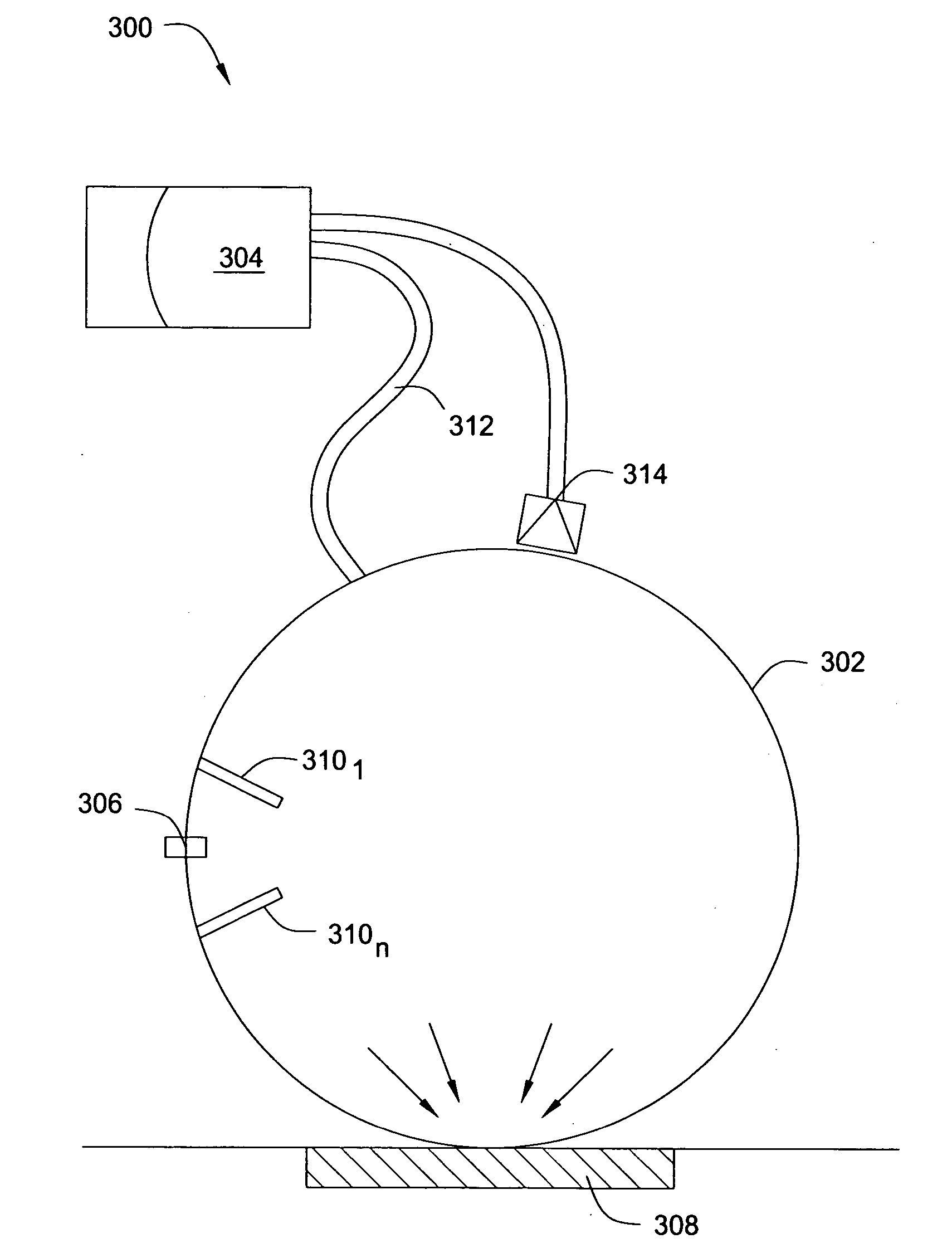
[0014] In one embodiment, the invention is a spectrophotometer with an LED illuminator. Embodiments of the present invention provide for a spectrophotometer that illuminates specimens using an LED source, rather than a xenon source, thereby conveying advantages in terms of cost, reliability and physical practicality. Moreover, the spectrophotometer is capable of resolving light reflected by the specimen into a number of spectral bands, where the number of spectral bands is not limited by the number of LEDs used to illuminate the specimen.

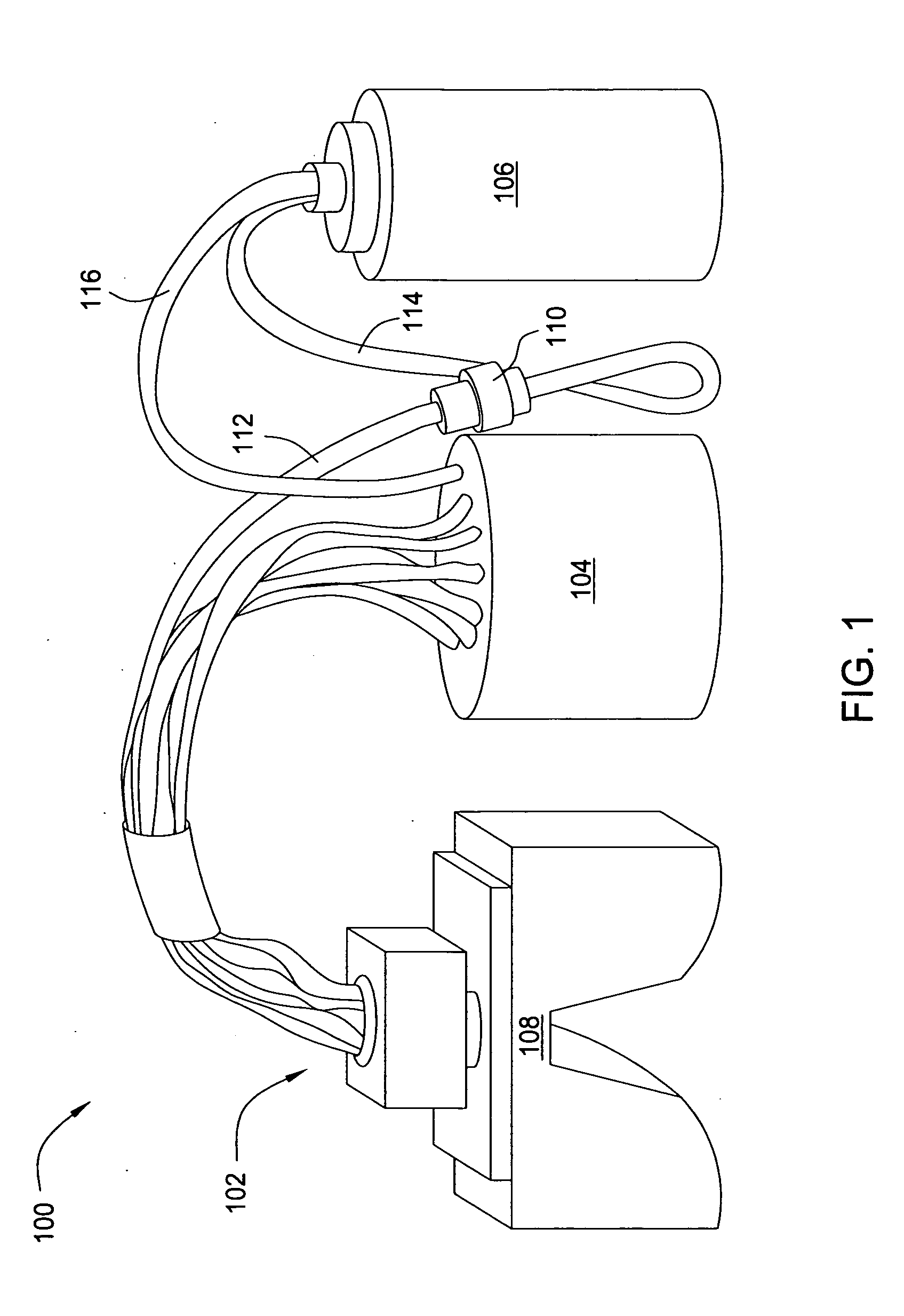
[0015]FIG. 1 is a schematic diagram illustrating one embodiment of a spectrophotometer 100, according to the present invention. The spectrophotometer 100 generally comprises a light emitting diode (LED) optical assembly 102, a measurement head 104 and a spectrum analyzer 106.

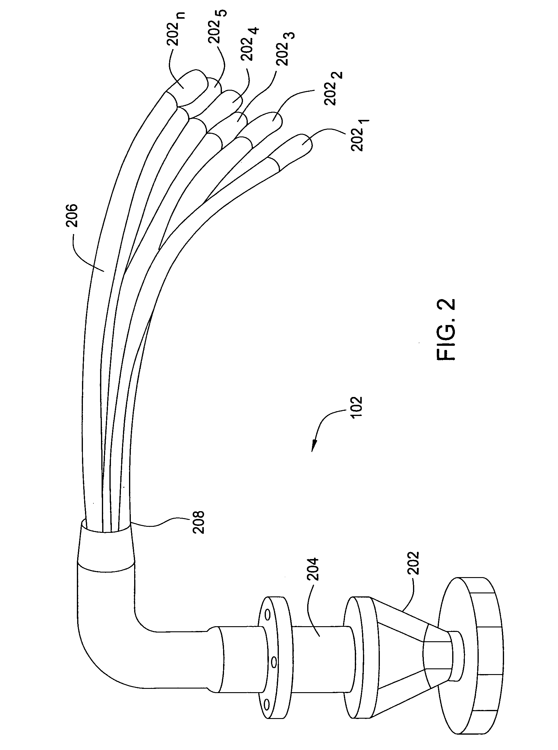
[0016] The LED optical assembly 102 is mounted to a mechanical mounting 108, which is in turn coupled to a power source (not shown) that provides power to the LED optical asse...


PUM


Abstract

In one embodiment, the invention is spectrophotometer with a light emitting diode illuminator. In one embodiment, a spectrophotometer for characterizing a reflectance spectrum of a specimen includes an optical assembly for illuminating the specimen, where the optical assembly includes at least one light emitting diode. A measurement head is coupled to the optical assembly for collecting light reflected by the specimen, and a spectrum analyzer is coupled to the measurement head for performing spectral analysis of the collected light into a plurality of spectral bands. A reference channel provides illumination from the optical assembly to the spectrum analyzer, while a test channel provides the collected light from the measurement head to the spectrum analyzer.

Description

CROSS REFERENCE TO RELATED APPLICATIONS [0001] This application claims the benefit of U.S. Provisional Patent Application No. 60 / 661,376, filed Mar. 14, 2005 (entitled “Spectrophotometer With Spectrum Analyzer In Which The Specimen Illuminator Comprises One Or More Light-Emitting Diodes”), which is herein incorporated by reference in its entirety.FIELD OF THE INVENTION [0002] The present invention relates generally to spectrophotometers and relates more specifically to illumination sources for use in spectrophotometers. BACKGROUND OF THE DISCLOSURE [0003] Spectrophotometers are commonly used in many industries to measure intensity as a function of the color, or more specifically, the wavelength of light. Typically, a spectrophotometer illuminates a specimen (which is either reflecting or transmitting) with a calibrated light source, and then measures the reflected light in order to characterize the specimen's reflectance spectrum. [0004] Conventional spectrophotometers employ a puls...

Claims


Application Information

Patent Timeline
Patent Type & Authority Applications(United States)
IPC IPC(8): G01J3/42
CPCG01J3/02G01J3/0218G01J3/0251G01J3/0297G01J3/10G01J3/42G01J3/50G01J3/501
Inventor INGLESON, ALAN
Owner DATACOLOR HOLDING AG
Learn More