Pipeline Ballast and Method of Use
a technology for installing ballast and pipelines, which is applied in the direction of pipe laying and repair, pipe supports, pipe/joints/fittings, etc., can solve the problems of requiring a large volume of ballast to provide sufficient, difficult to secure to the pipeline, and cataclysmic failure, etc., to achieve a lighter initial dry weight of ballast, reduce the effect of buoyancy and high density
- Summary
- Abstract
- Description
- Claims
- Application Information
AI Technical Summary
Benefits of technology
Problems solved by technology
Method used
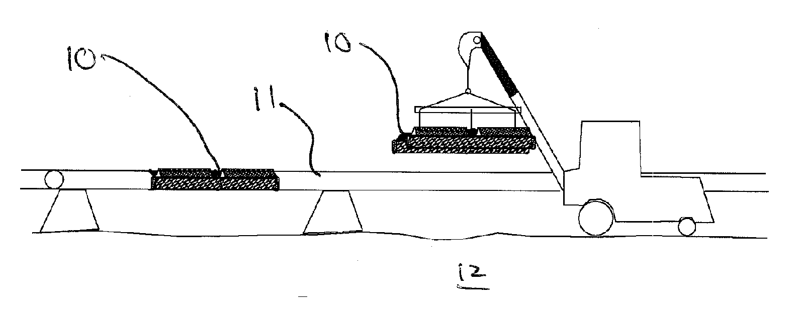
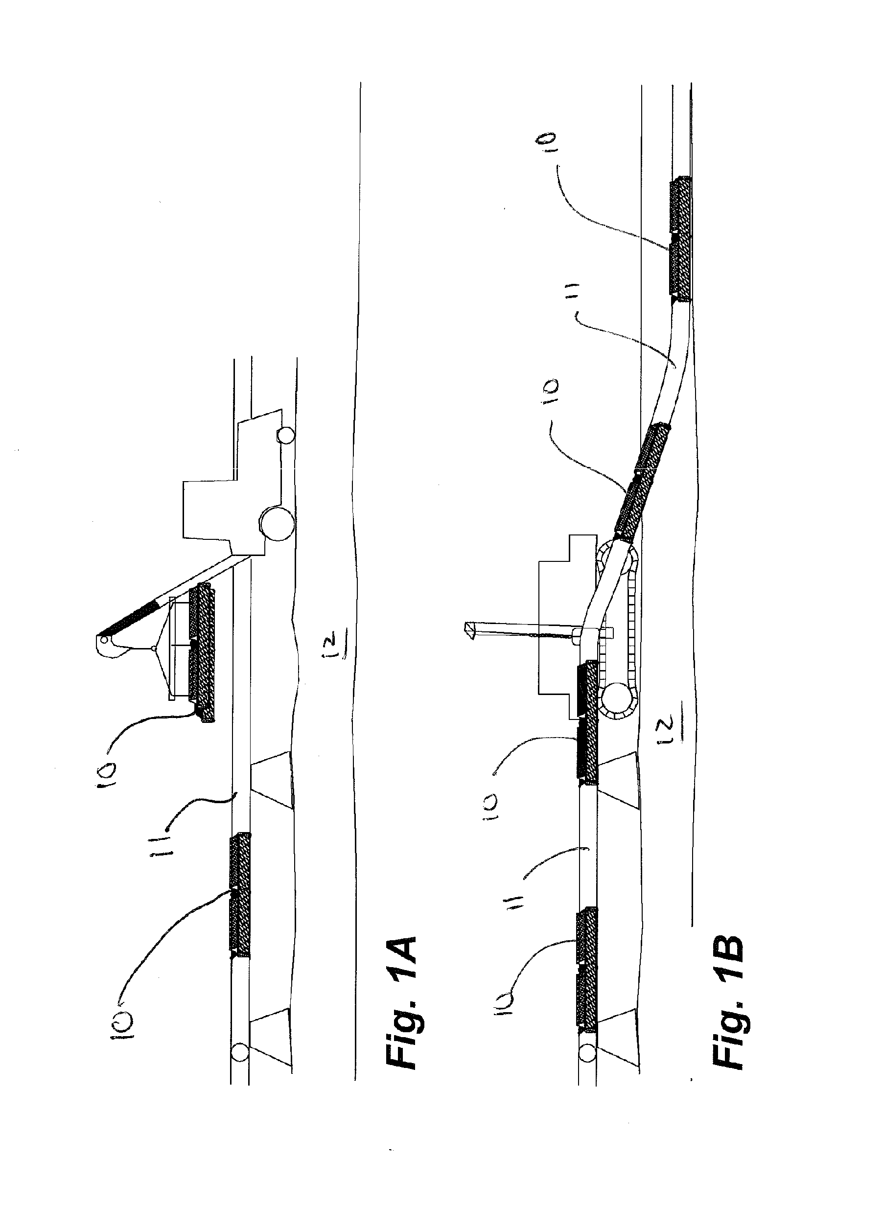
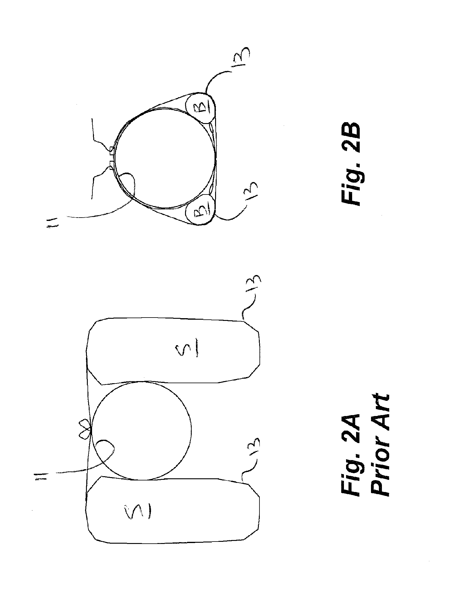
Image

Examples
example — 30
EXAMPLE—30 inch pipe with Barite and Sand Pipeline Ballast:
[0037] The following is to demonstrate the difference between high density Barite and Sand when used as a buoyancy restraining device.
Formulas used:
[0038] Bp=Vp*K*wlo
[0039] Bp=buoyancy of pipe lb / ft,
[0040] K=Environmental multiplier
[0041] wlo=specific weight liquid outside pipe lb / ft3
[0042] Bn=wp+(Vb*wli)
[0043] Bn=negative buoyancy lb / ft
[0044] wp=pipe weight lb / ft
[0045] wli=specific weight of liquid inside pipe
[0046] Wbd=(L*Wbs*wb) / (wb−(K*wlo))
[0047] Wbd=weight of dry ballast lb
[0048] L=ballast spacing, wb=specific weight of ballast material lb / ft3
[0049] Vp=(pi*Dˆ2) / (576)
[0050] Vp=displaced volume of pipe ft3 / ft
[0051] D=pipe O.D,
[0052] Vb=(pi*dˆ2) / 576
[0053] Vb=pipe bore volume ft3 / ft
[0054] d=pipe I.D
[0055] Wbs=Bp−Bn
[0056] Wbs=weight of submerged ballast lb / ft
[0057] Ref: KWH PIPE engineering formula for ballast design for driscoplex OD controlled pipe, March, 2002.
[0058] Assumptions:
[0059] Determine we...
PUM
 Abstract
Description
Claims
Application Information
 - R&D
- Intellectual Property
- Life Sciences
- Materials
- Tech Scout
- Unparalleled Data Quality
- Higher Quality Content
- 60% Fewer Hallucinations
Browse by: Latest US Patents, China's latest patents, Technical Efficacy Thesaurus, Application Domain, Technology Topic, Popular Technical Reports.
© 2025 PatSnap. All rights reserved.Legal|Privacy policy|Modern Slavery Act Transparency Statement|Sitemap|About US| Contact US: help@patsnap.com