
Image forming apparatus and droplet ejection control method

a technology of droplet ejection and forming apparatus, which is applied in the direction of measuring apparatus components, instruments, and inks, can solve the problems of pigment not easily formed uniformly or pulverized, water resistance and light resistance drawbacks, and difficult to form images with high saturation, etc., to achieve high resolution, prevent image distortion, and increase recording time

Inactive Publication Date: 2006-09-07
FUJIFILM CORP
View PDF7 Cites 20 Cited by
  • Summary
  • Abstract
  • Description
  • Claims
  • Application Information

AI Technical Summary

Benefits of technology

The present invention provides an image forming apparatus and a droplet ejection control method that can eject pigment ink containing fine particles of organic pigment with excellent monodispersion and high resolution without increasing recording time. The invention also prevents image distortion caused by pigment particles and deformation of dot shapes. The invention is achieved by a method of controlling the droplet ejection timing of a recording head based on the diameter change time of the droplets until they land on the recording medium. This prevents blurring caused by mixing of droplets and ensures a desired dot shape without reducing printing speed. The invention also utilizes a laminar flow channel to achieve a high purity of the organic pigment and prevent clogging of the nozzles in the recording head.

Problems solved by technology

As the coloring material for ink-jet ink, dyes have been used, but they have drawbacks as to water resistance and light resistance.
However, there are problems that the pigment is not easily formed uniformly or pulverized into fine-particles of a nanometer size (i.e., monodispersion), which can permeate pores in the surface of paper, and it is then difficult to form images with high saturation because the pigment is poor in permeability into the paper.
In the image formation by means of the inkjet recording apparatus, there are problems that if a plurality of dots are ejected so as to land in an overlapping manner on a recording medium, the ink droplets combine, the original circular shapes of the dots are lost (i.e., occurrence of deposition interference), and hence it becomes difficult to form the desired image with high resolution.
However, it is difficult to solve the problems concerning the deposition interference with the measures disclosed in Japanese Patent Application Publication Nos. 3-247450 and 2002-146222.
In particular, when the pigment ink containing the pigment particles of large particle size and poor monodispersion is used, it is difficult to form images with high saturation, and moreover, the deposition interference may be aggravated.
In the inkjet recording apparatus disclosed in Japanese Patent Application Publication No. 3-247450, the time for avoiding image distortion is determined for each parameter, but it is extremely difficult to determine a time for avoiding image distortion in relation to various types of dot patterns.
Furthermore, no sufficient explanation of the recording method is given in cases where mixed patterns combining different dot pitches and dot sizes are formed in one image.
However, since an adjacent dot cannot be deposited onto the paper until the existing dot on the surface of the paper has dried completely, then printing takes an extremely long time.
Furthermore, since the distance between the nozzles is determined by estimating the drying time based on one set of conditions, and since this is a fixed value, it is not possible to respond to cases where different ink or paper is used.
However, the method has such problems as that the contact time for the two solutions is not easily controlled, and thus subtle reaction control is difficult.
Therefore, it is difficult to stably produce fine particles of pigment of sufficient monodispersion.
In the related art as described above, there are unsolved problems of prevention of the deposition interference and production of fine particles of pigment, and it is hence difficult to obtain images of high resolution and high saturation by means of the pigment ink.

Method used


Image

  • Image forming apparatus and droplet ejection control method
  • Image forming apparatus and droplet ejection control method
  • Image forming apparatus and droplet ejection control method

Examples


example 2

[0287] At room temperature, 0.15 g of 2,9-dimethylquinacridone was dissolved into 13.35 mL of dimethylsulfoxide, 1.65 mL of a 0.8 mol / L aqueous potassium hydroxide solution, and 0.75 g of polyvinyl pyrrolidone (K30, manufactured by Wako Pure Chemicals Industries, Ltd.). The resultant solution is designated to IB solution. The pH of the IB solution was over a measurable limit, and was unable to be measured. This IB solution and the IIA solution prepared in Example 1 were separately passed through a micro-filter having pores of 0.45 μm diameter (manufactured by Fuji Photo Film Co., Ltd.), to remove impurities such as dust, thereby yielding transparent solutions, respectively. Then, using a reactor described below, reaction was conducted according to the following procedure. Two PTFE tubes with length 50 cm and equivalent diameter 1 mm were connected to two inlets of a PTFE Y-shaped connector with equivalent diameter 500 μm, each through a connector. Two syringes in which the IB soluti...

example 3

[0291] At room temperature, 0.01 g of 2,9-dimethylquinacridone was dissolved into 10.0 mL of dimethylsulfoxide, 0.1 1 mL of a 0.8N aqueous potassium hydroxide solution, and 0.05 g of polyvinyl pyrrolidone (K30, manufactured by Wako Pure Chemicals Industries, Ltd.). The resultant solution is designated to IC solution. The pH of the IC solution was over a measurable limit, and was unable to be measured. The IC solution was passed through a micro-filter having pores of 0.45 μm diameter (manufactured by Fuji Photo Film Co., Ltd.), to remove impurities such as dust, thereby yielding a transparent solution. In the reactor, as illustrated in FIG. 18A, which had a Y-shaped channel made of glass and had a channel width A of 100 μm, a channel width B of 100 μm, a channel width C of 100 μm, a channel length F of 12 cm, and a channel depth H of 40 μm, two PTFE tubes were connected to the introducing port 1011 and the introducing port 1012, each through a connector. Then, two syringes in which t...

example 4

[0293] Using the reactor, as illustrated in FIG. 19A, which had a cylindrical channel having a channel diameter D of 200 μm, a channel diameter E of 620 μm, and a channel length G of 10 cm, two PTFE tubes were connected to the introducing port 1021 and the introducing port 1022, each through a connector. Then, two syringes in which the IB solution or the IIA solution, as prepared in Examples 1 and 2, was put, respectively, were separately connected to the front tips of the tubes, and the reactor was fitted to a pump. The IB solution and the IIA solution were fed out at flow velocities of 1.0 mL / hour and 30.0 mL / hour, respectively. The inside of the channel was a laminar flow (Reynolds number: about 17.7), and a dispersion of 2,9-dimethylquinacridone was obtained. This was collected from the discharge port 1024. The pH of the dispersion was 10.44. This was measured by use of the dynamic light scattering particle diameter measuring device. As a result, the mode diameter of the particl...


PUM


Abstract

The image forming apparatus comprises a recording head which ejects droplets of a liquid onto a recording medium, the liquid containing fine particles of an organic pigment manufactured by the steps of: flowing a solution of an organic pigment dissolved in an alkaline or acidic aqueous medium through a channel which provides a laminar flow; and changing a hydrogen ion exponent (pH) of the solution in a course of the laminar flow.

Description

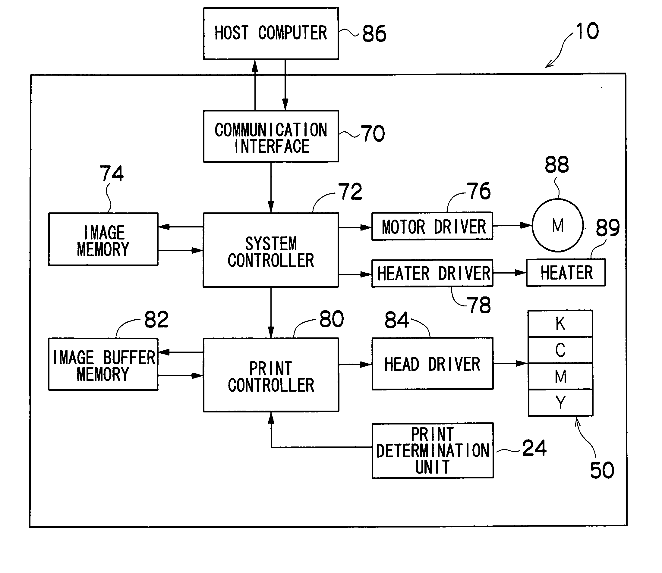
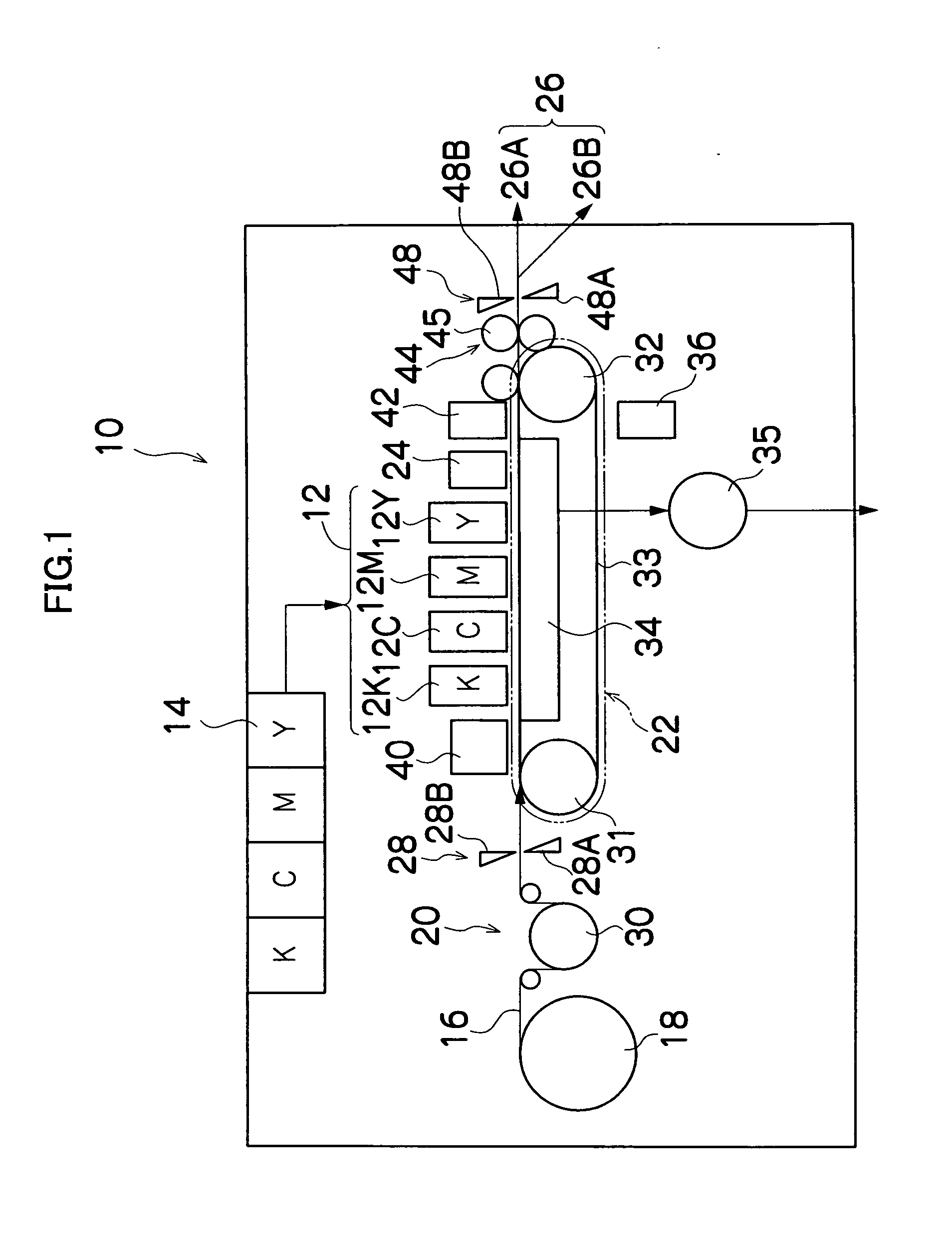
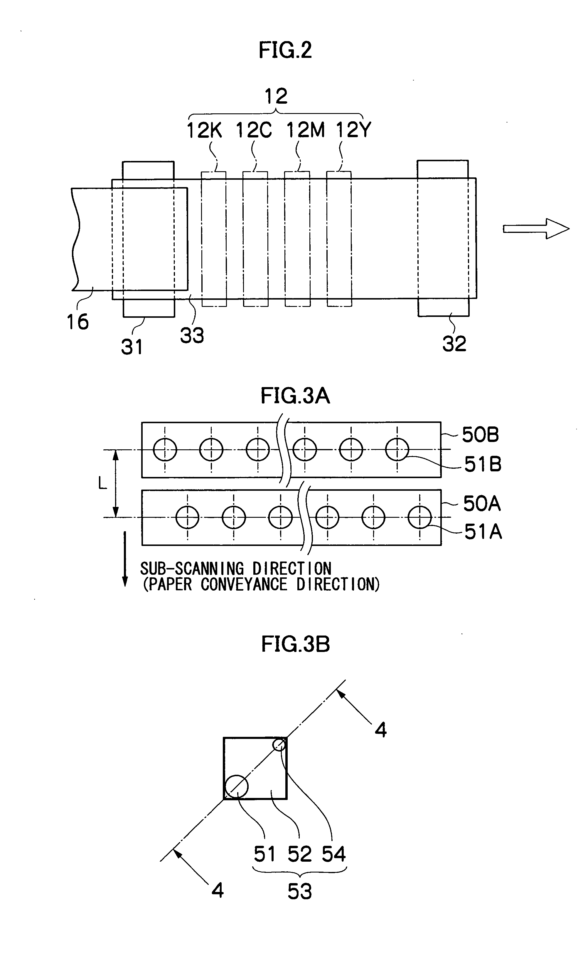
BACKGROUND OF THE INVENTION [0001] 1. Field of the Invention [0002] The present invention relates to an image forming apparatus and a droplet ejection control method, and more particularly to a recording control technology for an image forming apparatus and a droplet ejection control method for forming an image by means of dots formed with organic pigment ink on a recording medium. [0003] 2. Description of the Related Art [0004] Recently, inkjet recording apparatuses (inkjet printers) have become common as recording apparatuses for printing and recording images captured by digital still cameras, and the like. An inkjet recording apparatus comprises a plurality of recording elements (nozzles) in a head, the recording head being move to scan a recording medium while droplets of ink are ejected onto the recording medium from the recording elements, the recording medium being conveyed through a distance corresponding to one line, each time one line of an image is recorded onto a recordi...

Claims


Application Information

Patent Timeline
Patent Type & Authority Applications(United States)
IPC IPC(8): B41J29/38
CPCC09D11/30C09D11/322
Inventor KUSUNOKI, NAOKISATO, TADAHISAMAETA, HIDEKISHIMIZU, YUKI
Owner FUJIFILM CORP
Learn More