
Field effect transistors with vertically oriented gate electrodes and methods for fabricating the same

a gate electrode and field effect technology, applied in the field of thin body transistors, can solve problems such as inability to apply voltage, device prone to floating body effects, and operational and structural problems,

Inactive Publication Date: 2006-08-31
SAMSUNG ELECTRONICS CO LTD
View PDF19 Cites 29 Cited by
  • Summary
  • Abstract
  • Description
  • Claims
  • Application Information

AI Technical Summary

Benefits of technology

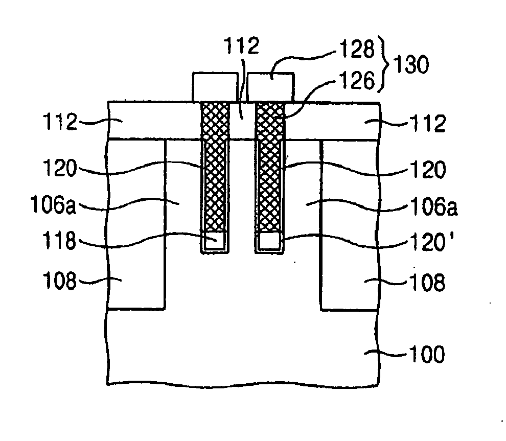
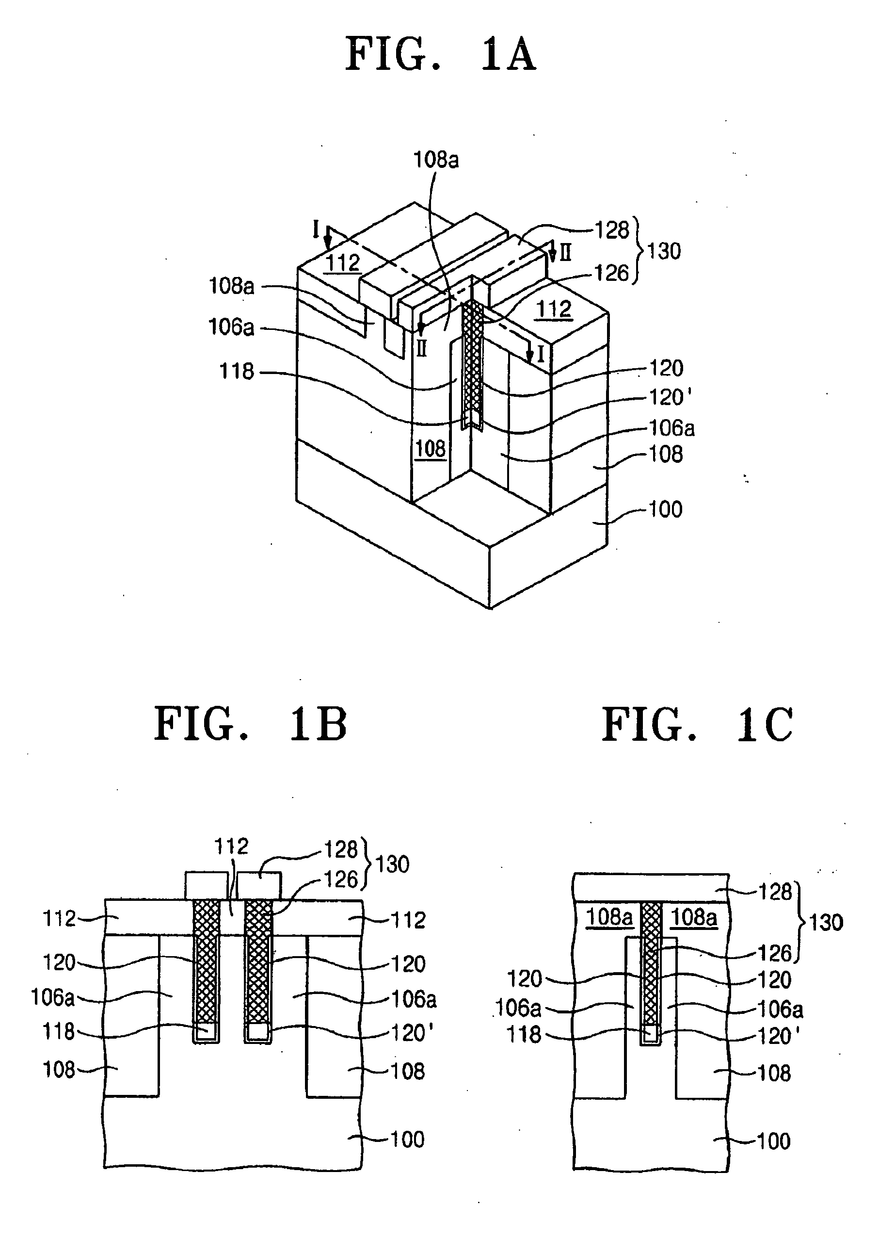
[0007] In some embodiments according to the present invention, a field effect transistor in a non-volatile EPROM may include a T-shaped gate electrode having a lateral portion on a top surface of a semiconductor substrate and having a vertical portion at least partially inside a cavity defined by opposing sidewalls of a vertically protruding portion of the substrate. In other embodiments, the T-shaped gate electrode may be a first T-shaped gate electrode and the cavity may be a first cavity. The transistor may further include a second T-shaped gate electrode having a lateral portion on a top surface of the substrate and having a vertical portion at least partially inside a second cavity defined by opposing sidewalls of the vertically protruding portion of the substrate. The lateral portion of the second T-shaped gate electrode may be substantially parallel to the lateral portion of the first T-shaped gate electrode, and the vertical portion of the second T-shaped gate electrode may be substantially parallel to the vertical portion of t

Problems solved by technology

However, as semiconductor devices become more highly integrated, a variety of operational and structural problems may arise.
However, such devices may be susceptible to floating body effects, which may be caused by heat generated during device operation and / or an accumulation of high-energy hot carriers.
In addition, a back bias voltage cannot be applied to compensate for changes in threshold voltage because of the insulator layer, so device performance may be affected.
Also, problems associated with stress due to differences in thermal expansion coefficients between the substrate and the insulating layer may occur.
Furthermore, since SOI field effect transistor technology may require connecting two substrates, processing costs may be increased and fabrication may become relatively complicated.

Method used


Image

  • Field effect transistors with vertically oriented gate electrodes and methods for fabricating the same
  • Field effect transistors with vertically oriented gate electrodes and methods for fabricating the same
  • Field effect transistors with vertically oriented gate electrodes and methods for fabricating the same

Examples


Embodiment Construction

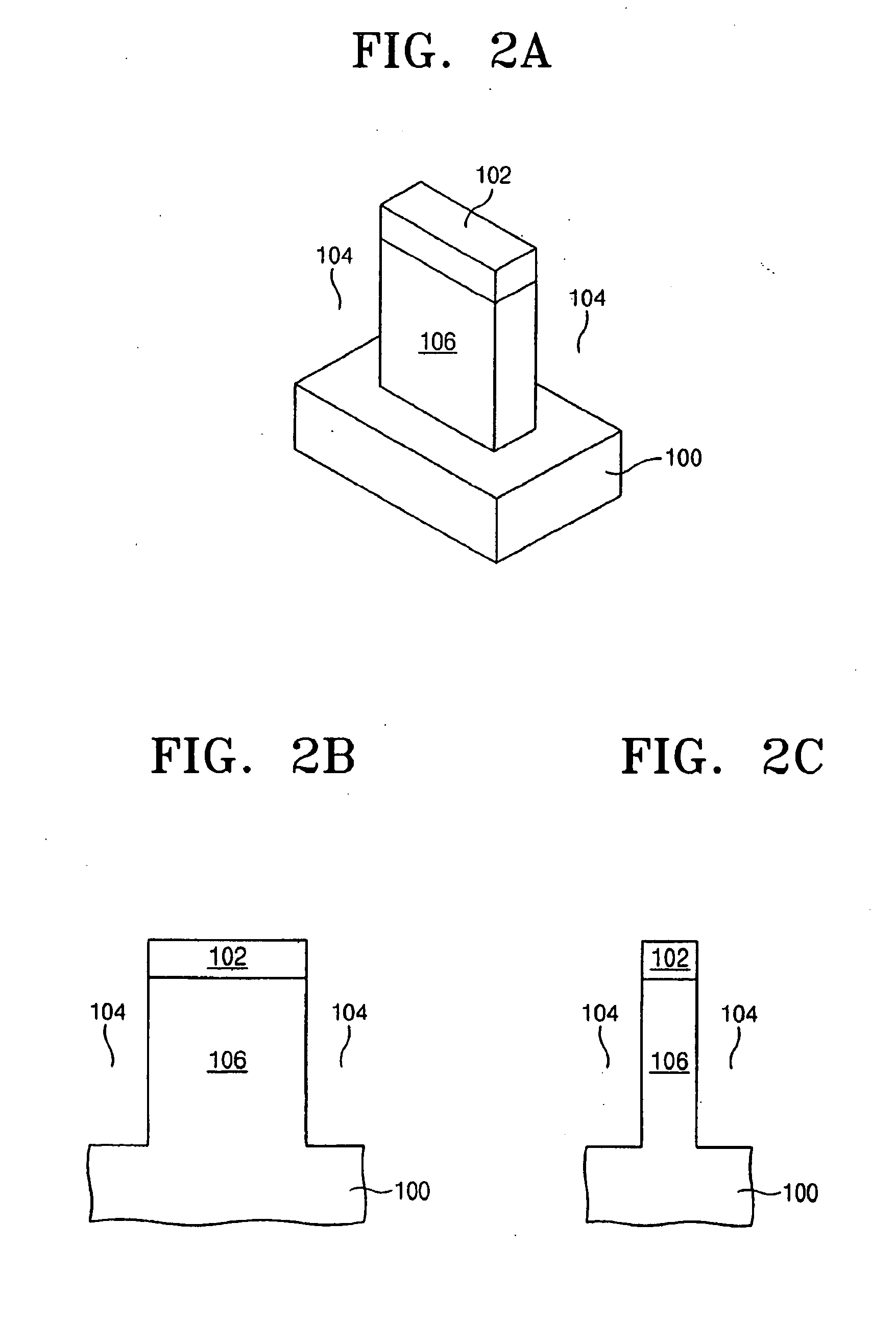
[0089] The present invention now will be described more fully hereinafter with reference to the accompanying drawings, in which preferred embodiments of the invention are shown. This invention may, however, be embodied in many different forms and should not be construed as limited to the embodiments set forth herein; rather, these embodiments are provided so that this disclosure will be thorough and complete, and will fully convey the scope of the invention to those skilled in the art. In the drawings, the thickness of layers and regions are exaggerated for clarity. It will be understood that when an element such as a layer, region or substrate is referred to as being “on” another element, it can be directly on the other element or intervening elements may also be present. It will be understood that when an element such as a layer, region or substrate is referred to as “under” another element, it can be directly under the other element or intervening elements may also be present. It...


PUM


Abstract

In semiconductor devices, and methods of formation thereof, both planar-type memory devices and vertically oriented thin body devices are formed on a common semiconductor layer. In a memory device, for example, it is desirable to have planar-type transistors in a peripheral region of the device, and vertically oriented thin body transistor devices in a cell region of the device. In this manner, the advantageous characteristics of each type of device can be applied to appropriate functions of the memory device.

Description

CROSS-REFERENCE TO RELATED APPLICATIONS [0001] This application is a continuation-in-part application of U.S. Ser. No. 10 / 945,246, filed Sep. 20, 2004, and further claims priority under 35 U.S.C. §119 to Korean Patent Application 10-2005-0029721 filed on Apr. 9, 2005, the entire contents of each being incorporated herein by reference.BACKGROUND OF THE INVENTION [0002] The present invention relates to semiconductor devices, and more specifically, to thin body transistors and methods for fabricating the same. [0003] In recent years, semiconductor devices have become highly integrated to achieve a combination of high-performance, high-speed, and economic efficiency. However, as semiconductor devices become more highly integrated, a variety of operational and structural problems may arise. For example, as the channel length of a typical planar field effect transistor becomes shorter, short channel effects, such as punch-through, may occur, parasitic capacitance, for example junction cap...

Claims


Application Information

Patent Timeline
IPC IPC(8): H01L29/94
CPCH01L21/823437H01L21/823487H01L21/84H01L27/105H01L27/10876H01L27/10894H01L27/1203H01L29/66621H01L27/1052H10B12/053H10B12/09H10B99/00
Inventor KIM, SUNG-MINPARK, DONG-GUNKIM, DONG-WONKIM, MIN-SANGYUN, EUN-JUNG
Owner SAMSUNG ELECTRONICS CO LTD
Learn More