
In-situ wafer parameter measurement method employing a hot susceptor as radiation source for reflectance measurement

a hot susceptor and measurement method technology, applied in the direction of optical radiation measurement, muffle furnace, furnace, etc., can solve the problems of reducing fabrication yield, wafer temperature control during processing, and increasing the requirements for wafer-to-wafer repeatability, so as to improve signal-to-noise ratio, reduce optical losses, and improve the effect of background radiation blocking

Inactive Publication Date: 2006-08-24
ENGELHARD CORP
View PDF25 Cites 14 Cited by
  • Summary
  • Abstract
  • Description
  • Claims
  • Application Information

AI Technical Summary

Benefits of technology

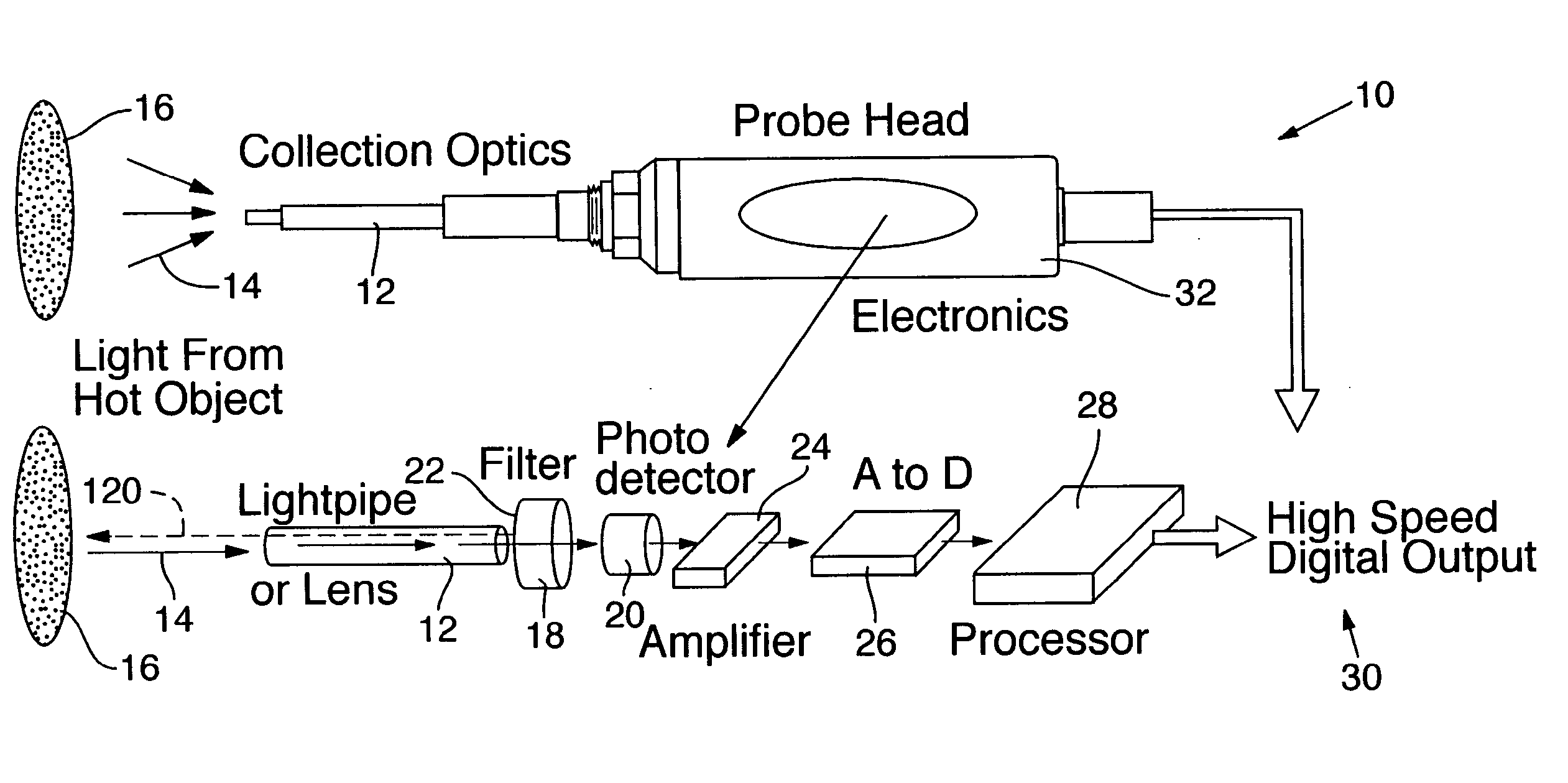
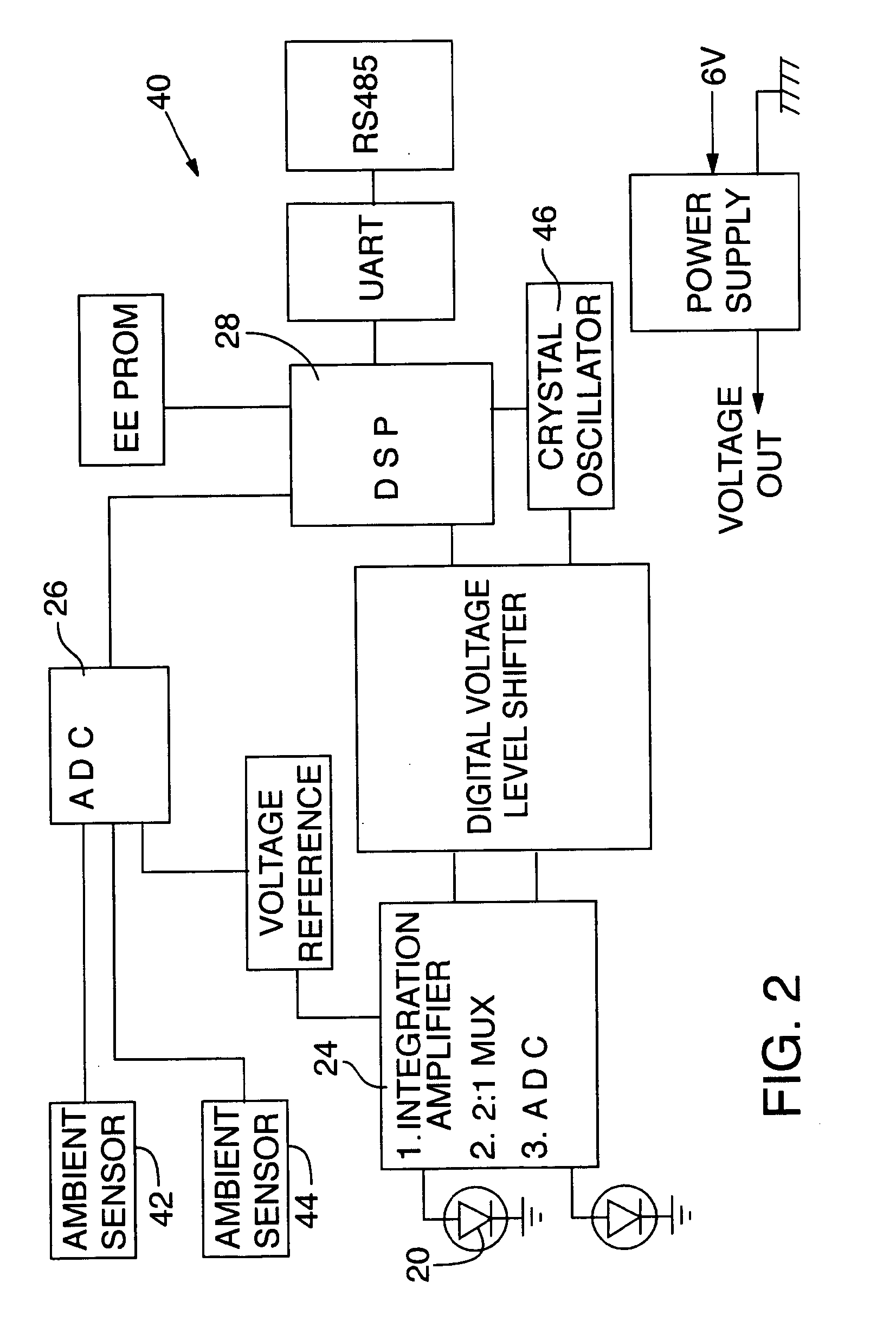
[0017] An advanced pyrometer system suitable for use with this invention has reduced optical losses, better background radiation blocking, improved signal-to-noise ratio, and improved signal processing to achieve improved accuracy and temperature measurement capabilities ranging from about 10° C. to about 4,000° C.

Problems solved by technology

As wafer sizes increase and the critical dimension of very large scale ICs scales deeper into the sub-micron range, the requirements for wafer-to-wafer temperature repeatability during processing become ever more demanding.
Inadequate wafer temperature control during processing reduces fabrication yields and directly translates to lost revenues.
Thermocouples are easy to use, but their reliability and accuracy are sometimes questionable because of measurement delays.
While conventional optical pyrometers are often superior to the use of thermocouples, there are measurement inaccuracy problems caused by background light, wafer transmission, emissivity, and signal-to-noise ratio.
However, numerous problems and limitations are still encountered when measuring wafer temperature using “Planck” radiation (light) emitted by the wafer.
There are numerous problems when measuring wafers at temperatures below about 400° C.: (1) minimal signal levels generated by the photo detector because the very small amount of radiation emitted by the wafer; (2) the wafer is semi-transparent at low temperatures and long wavelengths (greater than 900 nm); and (3) the background light is often larger than the emitted wafer signal and causes large errors when the background light enters the collection optics.
Moreover, the often unknown emissivity of the object being measured increases the difficulty of achieving accurate temperature measurements.

Method used


Image

  • In-situ wafer parameter measurement method employing a hot susceptor as radiation source for reflectance measurement
  • In-situ wafer parameter measurement method employing a hot susceptor as radiation source for reflectance measurement
  • In-situ wafer parameter measurement method employing a hot susceptor as radiation source for reflectance measurement

Examples


example

[0137] A horizontal transporter 196 moves semiconductor wafer 160 by its peripheral margins into position above and spaced apart from hot susceptor 162 by the distance of gap 190, which typically ranges from about 2.54 cm (1.0 inch) to about 0.0254 mm (0.001 inch). Note that horizontal transporter 196 does not substantially block the surface of wafer 160 from hot susceptor 162 or radiometric system 10. As wafer 160 is moved horizontally into position, cool semiconductor wafer 160 emits some emitted radiation 198, which is sensed by radiometric system 10. Emitted radiation 198 is initially small and increases when semiconductor wafer 160 is heated during subsequent lowering toward hot susceptor 162. Before lowering semiconductor wafer 160, emitted radiation 174 from hot susceptor 162 that is reflected by semiconductor wafer 160 as reflected radiation 192 provides a baseline radiation measurement for comparing with measurements taken during the subsequent downward motion of semiconduc...


PUM


Abstract

Preferred embodiments of a semiconductor wafer temperature measurement method take advantage of the tight control of the surface conditions and temperature of a hot susceptor, which tight control provides known and reproducible radiation emissions from the hot susceptor. The known amount of radiation emitted by the hot susceptor is employed as a stable radiation source for making precise reflectance and emission measurements of the semiconductor wafer.

Description

RELATED APPLICATION [0001] This is a continuation-in-part of U.S. patent application Ser. No. 11 / 044,842, filed Jan. 26, 2005, abandoned, which is a continuation of U.S. patent application Ser. No.10 / 202,498, filed Jul. 23, 2002, abandoned, which claims benefit of U.S. Provisional Patent application No. 60 / 307,423, filed Jul. 23, 2001.TECHNICAL FIELD [0002] This invention relates to radiometric temperature measurement systems (also known as “pyrometers”) and, more particularly, to a method entailing measurement of reflected radiation originating from a hot susceptor and reflected by a target medium positioned in contact with the hot susceptor to obtain a target emissivity value for use in subsequent measurement of temperature of the target medium. BACKGROUND OF THE INVENTION [0003] Pyrometer-based temperature measurement systems have a long development history. For example, even before 1930, U.S. Pat. Nos. 1,318,516; 1,475,365; and 1,639,534 all described early pyrometers. In 1933, ...

Claims


Application Information

Patent Timeline
IPC IPC(8): G01K11/30G01J5/00G01K11/12
CPCF27B5/04F27B17/0025F27D19/00F27D21/00G01J5/0003G01K11/125
Inventor SCHIETINGER, CHARLES W.KNOPE, JAMES W.SPRINKLE, PATRICK
Owner ENGELHARD CORP
Learn More