
Method and apparatus for communicating control and other information over a power bus

Inactive Publication Date: 2006-08-24
NTH SOLUTIONS
View PDF34 Cites 47 Cited by
  • Summary
  • Abstract
  • Description
  • Claims
  • Application Information

AI Technical Summary

Benefits of technology

[0014] Those skilled in the art understand that one of the challenges to communicating signaling within a vehicle relates to the substantial amount of electrical noise the vehicle generates. Alternators, heater fan motors, ignition systems and light bar rotators all typically generate substantial amounts of noise that can interfere with signal communications from one point within a vehicle to another. Communications techniques provided by the illustrative non-limiting exemplary implementations described herein are able to communicate signals effectively and reliably over the main power bus used to supply power to all systems on board the vehicle. In accordance with one exemplary illustrative non-limiting alternate implementation, additional switches are provided to synchronously or asynchronously disconnect noisy vehicle loads from the power bus from time to time (e.g., during data transmissions) in order to reduce the amount of noise the voltage sensor/demodulator sees. Such additional techniques may be helpful

Problems solved by technology

Yet, it is also one of the most dangerous.
Collisions involving emergency vehicles and personal vehicles injure many people each year.
Manufacturers of emergency response vehicle equipment such as emergency warning lights, light bars, sirens, and the like, have spent considerable time and effort developing effective systems for warning of oncoming emergency response vehicles so motorists and pedestrians can get out of the way.
However, such manufacturers typically do not ship emergency response vehicles with light bars already installed.
Such customization can end up being expensive and time consuming because of the additional wiring and other vehicle customization that may be required.
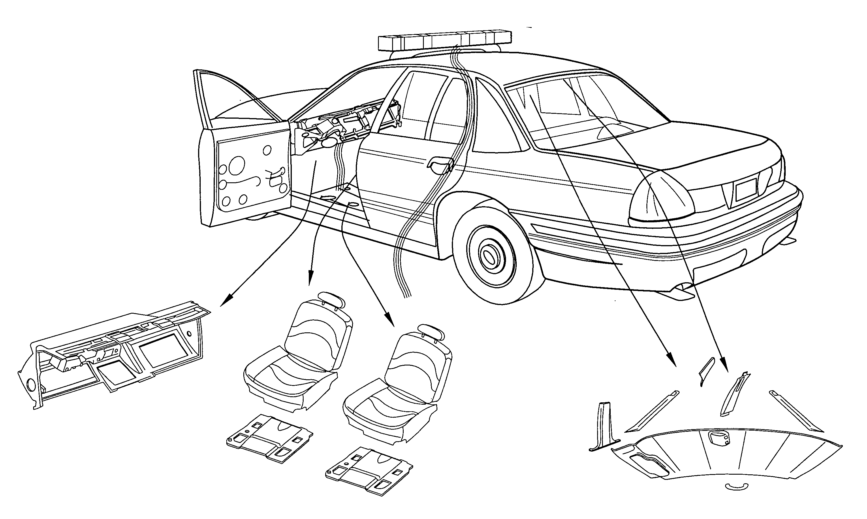
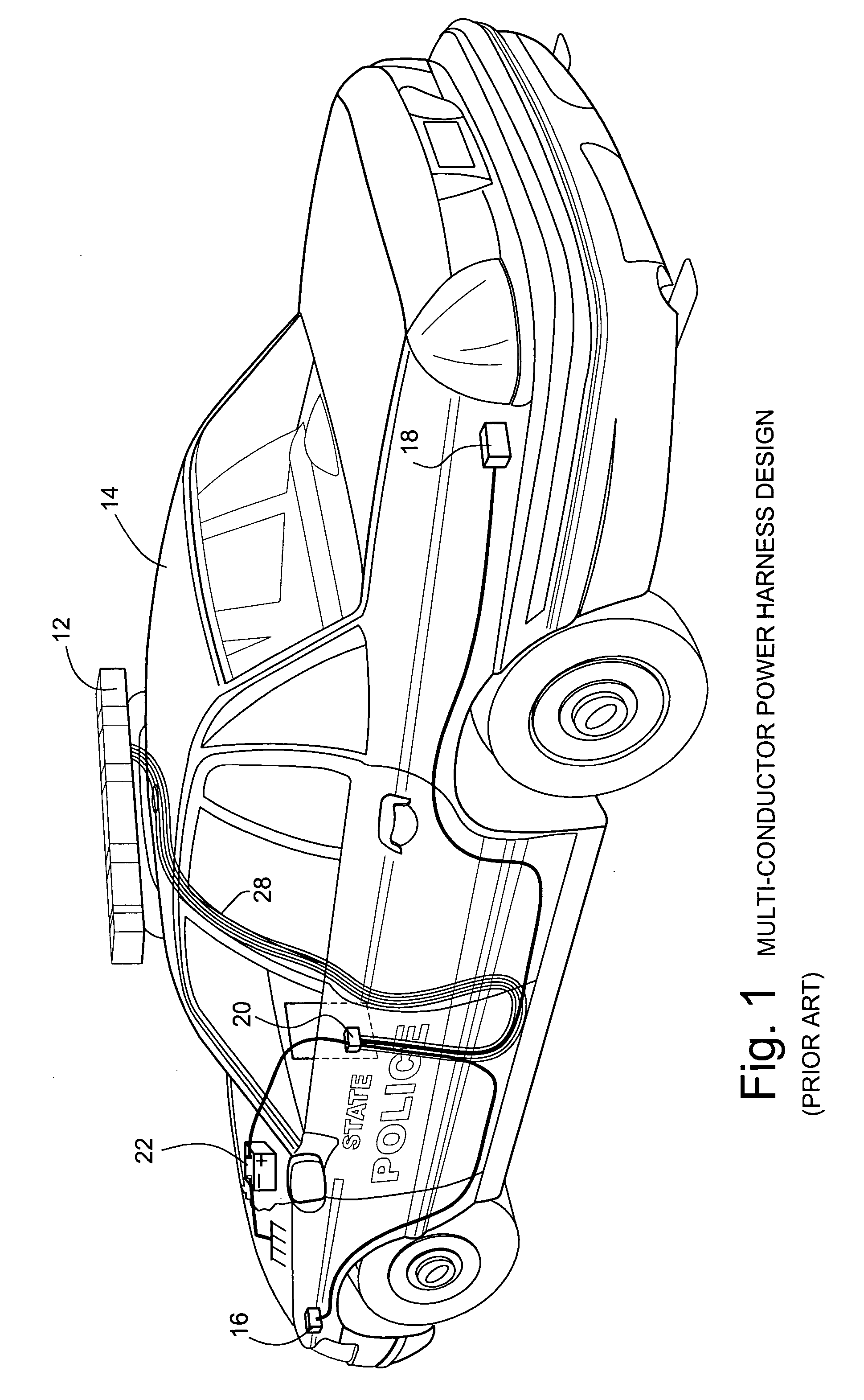
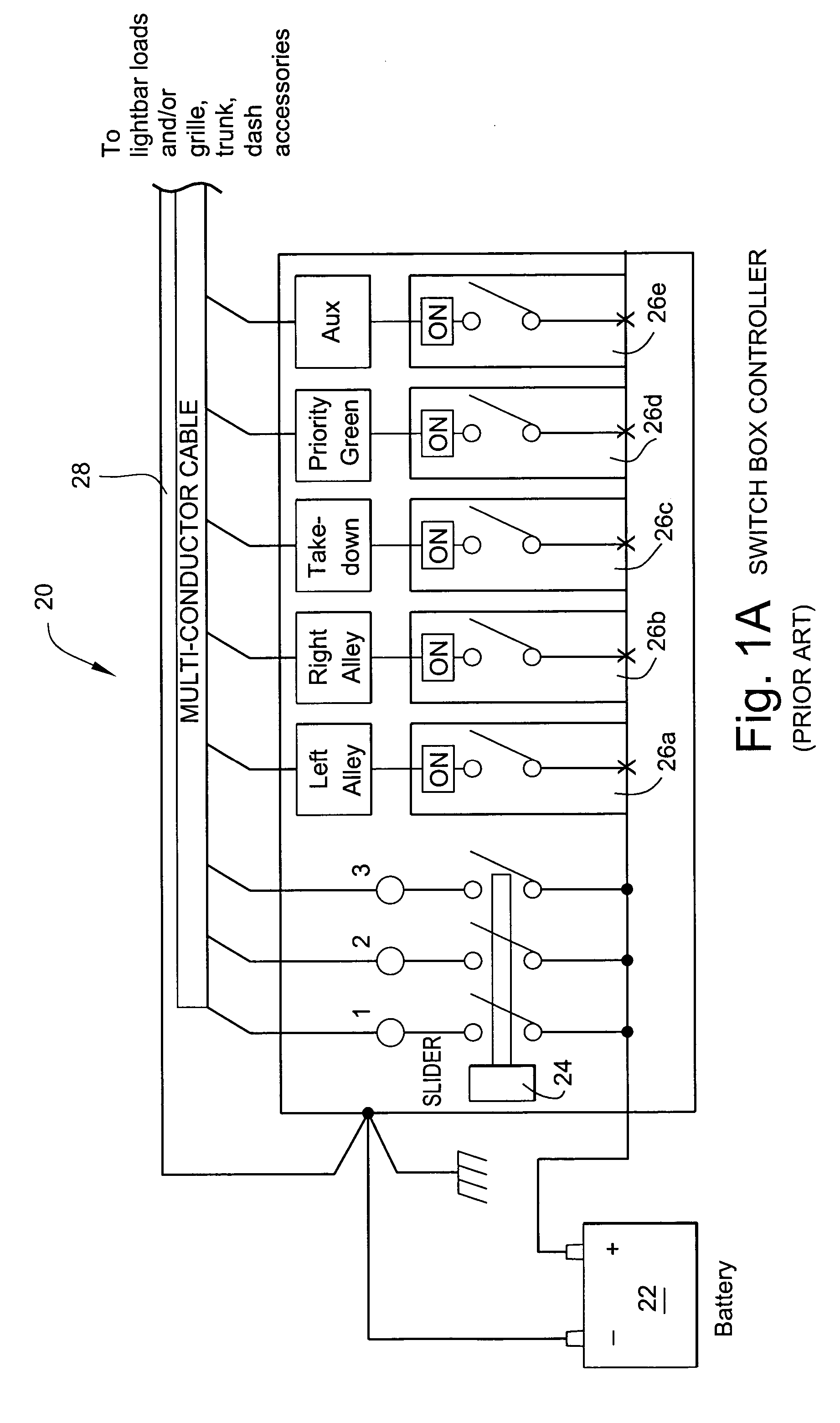
While this design is highly reliable and has worked well for a number of years, it has the disadvantage that the resulting multi-conductor bundle of cables must be routed throughout the vehicle to the devices being controlled. FIG. 2 shows one example of what can be involved in installing conventional light bars and associated control equipment in a standard conventional police interceptor-type vehicle.
All of these operations are time consuming and therefore are not only expensive but may delay operational use of the vehicle by emergency response personnel.
Such cable routing can be costly due to the need to conceal the cables within headliners and other interior portions of the vehicle.
Such installation may require a number of hours of work by a skilled technician.
It is not unusual for initial installation efforts to be unsuccessful, requiring the partial or entire disassembly / reassembly process to be repeated in order to relieve crimped cables, bad connections, cosmetic bumps and blemishes, etc.
If such wiring fails after installation, the same sort of disassembly process may be required to repair or replace the wiring harness.
This can result in downtime during which the vehicle cannot be used.
Those skilled in the art understand that one of the challenges to communicating signaling within a vehicle relates to the substantial amount of electrical noise the vehicle generates.
Alternators, heater fan motors, ignition systems and light bar rotators all typically generate substantial amounts of noise that can interfere with signal communications from one point within a vehicle to another.

Method used


Image

  • Method and apparatus for communicating control and other information over a power bus
  • Method and apparatus for communicating control and other information over a power bus
  • Method and apparatus for communicating control and other information over a power bus

Examples


Embodiment Construction

[0030]FIG. 3 shows an example police vehicle using the current modulated load communication technique described herein to communicate control signals between a dash or console mounted controller and a roof-mounted light bar. In the example shown, the multi-conductor cable power control bundle 28 is eliminated as no longer being needed or required. Instead, control signals are communicated via the main power bus that connects the battery to the light bar. Additional control signals may be communicated via the same bus to other devices located at various points within the vehicle. For example, a rear-mounted warning lamp, front headlight flashers, etc. may all be controlled via the same control mechanism and communications path over the main power bus of the vehicle. The cabling shown can be factor-installed single or two-conductor power cables, and the data transmitter connection may be a two-conductor connection to the local power bus as is conventional.

[0031] In the FIG. 3 arrange...


PUM


Abstract

An information signal to be communicated to a roof-mounted light bar or other electrical or electronic device travels over the vehicle's or other environment's power bus or other power conductor. In one exemplary illustrative non-limiting implementation, a modulated current load draws power supply current in an amount that is instantaneously responsive to at least some characteristic of the information signal to be communicated. This modulated current loading induces the vehicular or other power supply (e.g., DC battery) to modulate its output voltage in a manner that is responsive to the modulated current loading. A voltage sensor and demodulator also connected to the power bus senses the resulting voltage fluctuations and demodulates those fluctuations to recover or regenerate the original information signal. The recovered information signal may be used for any purpose including but not limited to controlling aspects of the operation of an emergency vehicle light bar or other audible and / or visual warning system or other device. The data sender and data receiver can be co-located to provide a full duplex or half duplex powerline communicated transceiver.

Description

CROSS-REFERENCES TO RELATED APPLICATIONS [0001] Not applicable. STATEMENT REGARDING FEDERALLY SPONSORED RESEARCH OR DEVELOPMENT [0002] Not applicable. FIELD [0003] The technology herein relates to communicating information-bearing signals such as control signals over the power bus of a vehicle or other environment, and more particularly to modulating a current load with the information signal to induce a mirrored voltage modulation. Example applications include controlling devices including, but not limited to, emergency response lighting and / or sound-based warning systems such as, for example, police and other emergency response vehicle light bars. BACKGROUND AND SUMMARY [0004] We count on our police, firefighting and emergency medical response teams every day. Ambulance and fire department emergency response teams save countless lives and prevent property damage. Emergency response teams are able to help because of their skills, their training and their equipment. In the highly de...

Claims


Application Information

Patent Timeline
IPC IPC(8): B60Q5/00H02J3/02B60L1/00G05B11/01G08B1/08
CPCB60L2250/16B60R16/03H02J13/0003H04B3/548H04B2203/547Y02T90/16H04B2203/5416H04B2203/5458B60Q1/2611H02J2310/46H02J13/00016
Inventor CANFIELD, ERIC L.
Owner NTH SOLUTIONS
Learn More