
High temperature chemical vapor deposition apparatus

a chemical vapor deposition and high temperature technology, applied in chemical vapor deposition coatings, coatings, metallic material coating processes, etc., can solve the problems of chemical non-uniformity, thickness and chemistry non-uniformity, etc., to maximize precursor flow and maximize dopant deposition

Inactive Publication Date: 2006-08-24
MOMENTIVE PERFORMANCE MATERIALS INC
View PDF18 Cites 14 Cited by
  • Summary
  • Abstract
  • Description
  • Claims
  • Application Information

AI Technical Summary

Benefits of technology

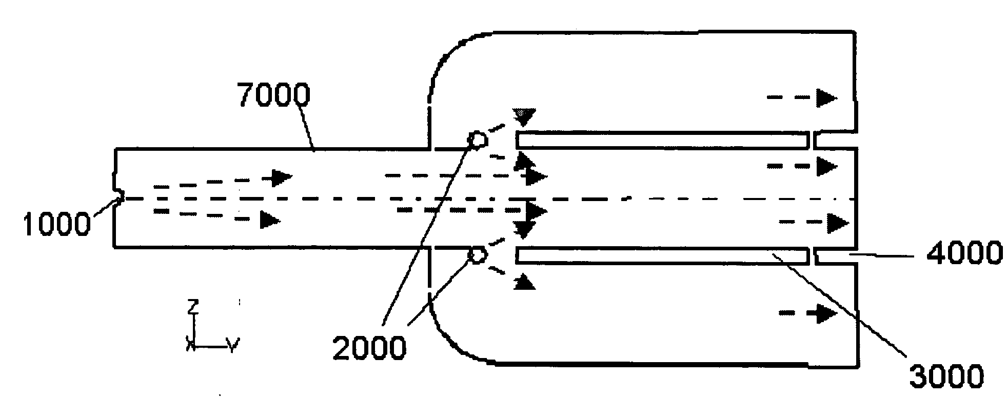
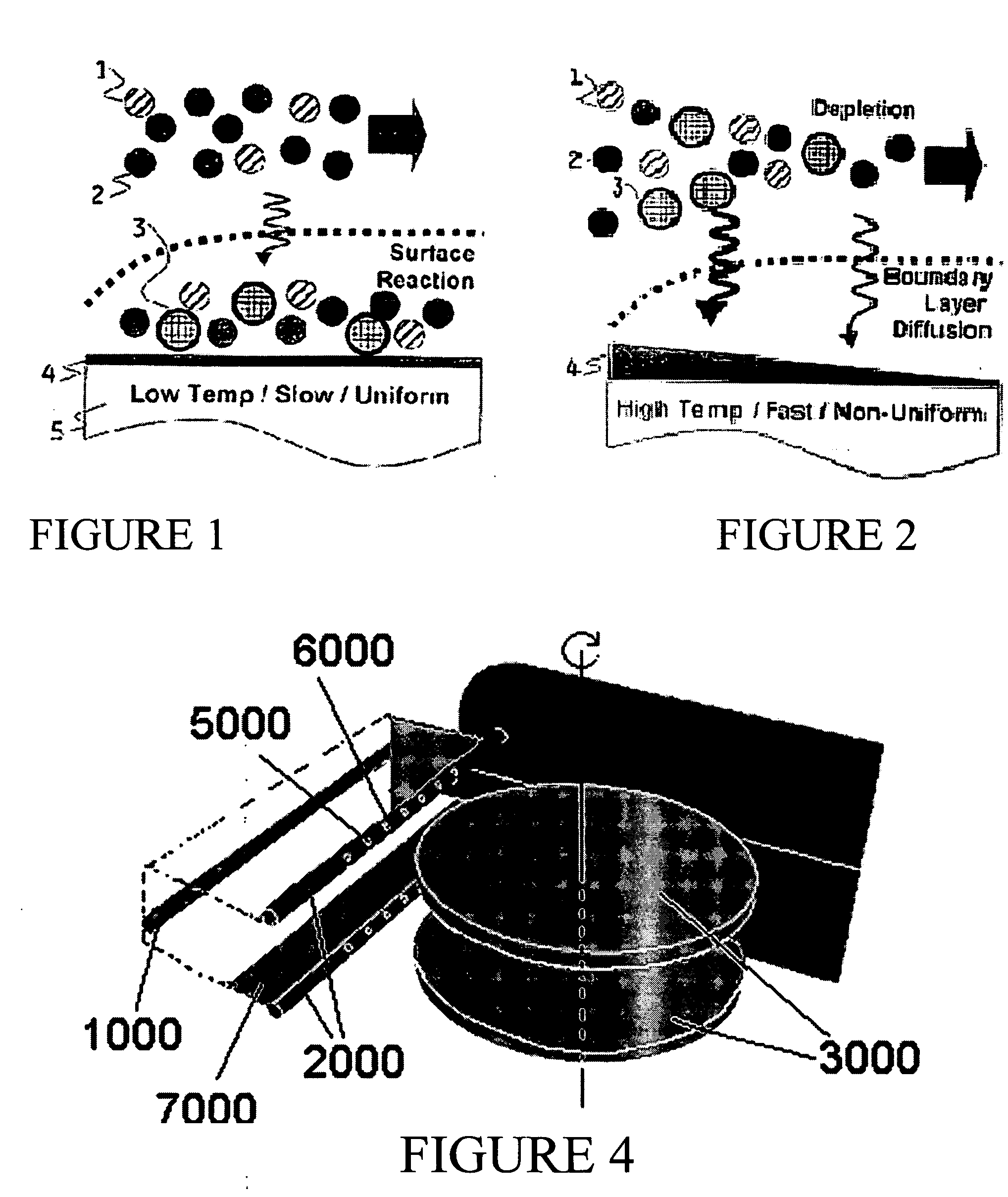
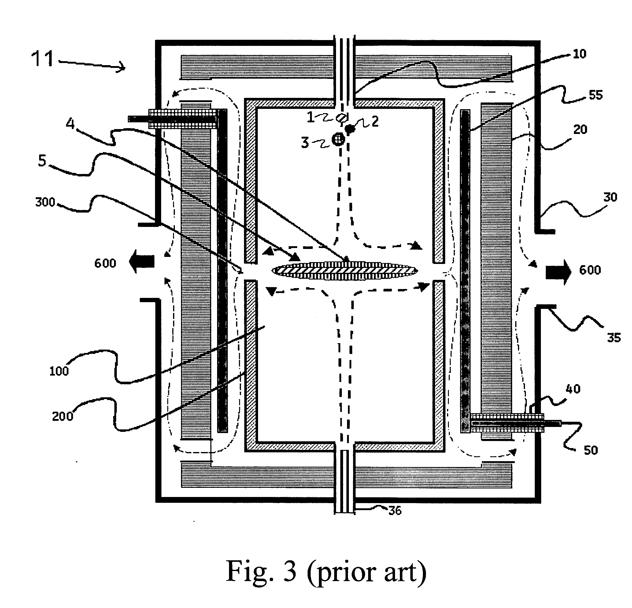
The invention is about a high temperature chemical vapor deposition (CVD) system that can coat substrates with various materials. The system includes a vacuum reaction chamber, a reactant feed supply system, an outlet unit, heating means, and a feeding system with multiple injection means for gases. The system can also have a sacrificial substrate to create a uniform coating and a vacuum vessel for the deposition of doped coating layers. The invention also includes a divider-plate to maximize precursor flow and a differential placement of reactant feeds for carbon-doped pyrolytic boron nitride coating. The system can create a uniform thickness and chemical composition across the substrate with similar deposition profiles for BN and C.

Problems solved by technology

However, the deposited material in the reactor chamber of the prior art typically suffers from non-uniformities in thickness and chemistry, i.e. the deposited thickness and chemistry uniformities, expressed as the ratio of standard deviation to average, are typically larger than 10%.
The chemical non-uniformity issue is especially important when mixtures of gases are used for the formation of materials with relatively complex chemistries, i.e., doped materials.

Method used


Image

  • High temperature chemical vapor deposition apparatus
  • High temperature chemical vapor deposition apparatus
  • High temperature chemical vapor deposition apparatus

Examples


example 1

[0089] In an illustrative example of a process to deposit layers in various configurations of the CVD apparatus of the invention, the heated inner walls of the chamber 11 is first heated to 1800° C. The pressure in the exhaust line is controlled to a pressure in the 300 to 450 m Torr range. Gaseous feed CH4 and N2 are supplied at 5 slm and 2 slm respectively through the first injector 1000. BCl3, NH3 and N2 are supplied at 2 slm, 5.5 slm and 3 slm respectively through a set of two secondary injectors 2000. The feeds are mixed prior to enter the inlet of the injector pipes.

[0090] The injector are graphite pipes having a length of 63 cm, a diameter of 1″, with a plurality of feed holes each 1 cm in diameter, and placed apart at 2″ on 2000 and 1″ on 1000. The leading edge of substrate 3000 having a 450 mm diameter is located at a distance of 2″ from the secondary injectors. The first injector is spaced at further away from the secondary injectors 2000, providing enough residence time ...

example 2

[0096] In this example, the sensitivity of the resistance characteristics of the film is studied with the flow rates of the C dopant (as CH4 feed) in injector system 1000 varying from 3 slm to 7 slm. It is found that increasing the CH4 flow rate increases the C precursor concentration near the substrate, which in turn, increasing the C % in the film and hence the average resistance of the film decreases with the concentration. Also, it is found that the resistance ratio (max. / min) increases with the flow rates. Therefore, the dopant CH4 flow rate—as fed through the injector system 1000 being placed further away from the substrate, is an effective design parameter which gives a good control on the C deposition on the substrate, and subsequently, the resistance characteristics of the coated film.

[0097]FIG. 11 illustrates the sensitivity of resistance of the CPBN film on the substrate to the flow rate of CH4 from the first injector system. FIG. 12 is a graph illustrating the resistanc...

example 3

[0098] In another illustrative example, a detailed set of design of experiments (DOE) was carried out with the two design factors in Example 1. In this example, a CPBN film on the substrate is desired, which has resistance characteristics as described in FIG. 11. The C percentage in the film is related to the resistivity as in FIG. 10. This resistivity and the film thickness can be used to estimate the resistance of the film on the substrate. These calculations are summarized as in FIG. 12. A parametric analysis is carried out to study the effect of two parameters of the apparatus—the distance between the substrates and lead distance of the first injector from the substrate—on the resistance characteristics of the deposited film. These two parameters have strong influence on the resistance of the deposited film as seen from the minimum and maximum resistances on the substrate.


PUM

PropertyMeasurementUnit
pressureaaaaaaaaaa
temperatureaaaaaaaaaa
temperaturesaaaaaaaaaa

Abstract

Embodiments for an apparatus and method for depositing one or more layers onto a substrate or a freestanding shape inside a reaction chamber operating at a temperature of at least 700° C. and 100 torr are provided. The apparatus is provided with a feeding system having injection means for differential pre-reactions and / or pre-treating of a plurality of gases or gas mixtures, tailoring the distribution of a plurality of gas-phase species, yielding a deposit that is substantially uniform in thickness and chemical composition along the substrate surface. In one embodiment, the apparatus further comprises a sacrificial substrate that further helps achieving thickness and chemical uniformity on the substrate, by imitating a continuous surface to deposit on and thus preventing any disturbances in the flow pattern especially towards the edge of the substrate.

Description

CROSS REFERENCE TO RELATED APPLICATION [0001] This application claims priority to U.S. Provisional Patent Application No. 60 / 654654 with a filing date of Feb. 18, 2005 and U.S. Provisional Patent Application No. 60 / 752505 with a filing date of Dec. 21, 2005, which patent applications are fully incorporated herein by reference. This application is also a CIP of and claims priority to U.S. patent application Ser. No. 11 / 291558, with a filing date of Dec. 1, 2005.FIELD OF INVENTION [0002] The present invention relates to a high temperature CVD apparatus. BACKGROUND OF THE INVENTION [0003] Chemical vapor deposition (“CVD”) is a widely used production process for the application of a coating to a substrate, as well as for the fabrication of freestanding shapes. In a CVD process, the formation of the coating or the freestanding shape occurs as a result of chemical reactions between volatile reactants that are injected into a reactor containing a heated substrate and operating at sub-atmos...

Claims


Application Information

Patent Timeline
Patent Type & Authority Applications(United States)
IPC IPC(8): C23C16/00
CPCC23C16/342C23C16/452C23C16/45514C23C16/45578C23C16/4558C23C16/4584
Inventor MURALIDHARAN, LAKSHMIPATHYSARIGIANNIS, DEMETRIUSHUBBARD, PATRICIASCHAEPKENS, MARCPANT, ATUL
Owner MOMENTIVE PERFORMANCE MATERIALS INC
Learn More