
Air conditioning system for a seat

a technology of air conditioning system and seat, which is applied in the direction of chairs, transportation and packaging, vehicle arrangements, etc., can solve the problems of uneven air conditioning of seat or backrest surface, inability to implement cover stitching furrows through ventilation layer of knitted spacer fabric, and inability to achieve air circulation technology. , to achieve the effect of simple installation, simple steps for seat installation, and quick performan

Active Publication Date: 2009-11-17
GENTHERM GMBH
View PDF367 Cites 31 Cited by
  • Summary
  • Abstract
  • Description
  • Claims
  • Application Information

AI Technical Summary

Benefits of technology

[0007]The present invention provides an air-conditioned seat with at least one cushion layer subdivided by stitchings or the like, in which a uniform and sufficient supply of air to all air-circulating layers located under a cover material is ensured by as simple as possible construction. In particular, the flow connection through the cover stitching furrows is such that a single ventilation device is sufficient for the ventilation of all seat regions.
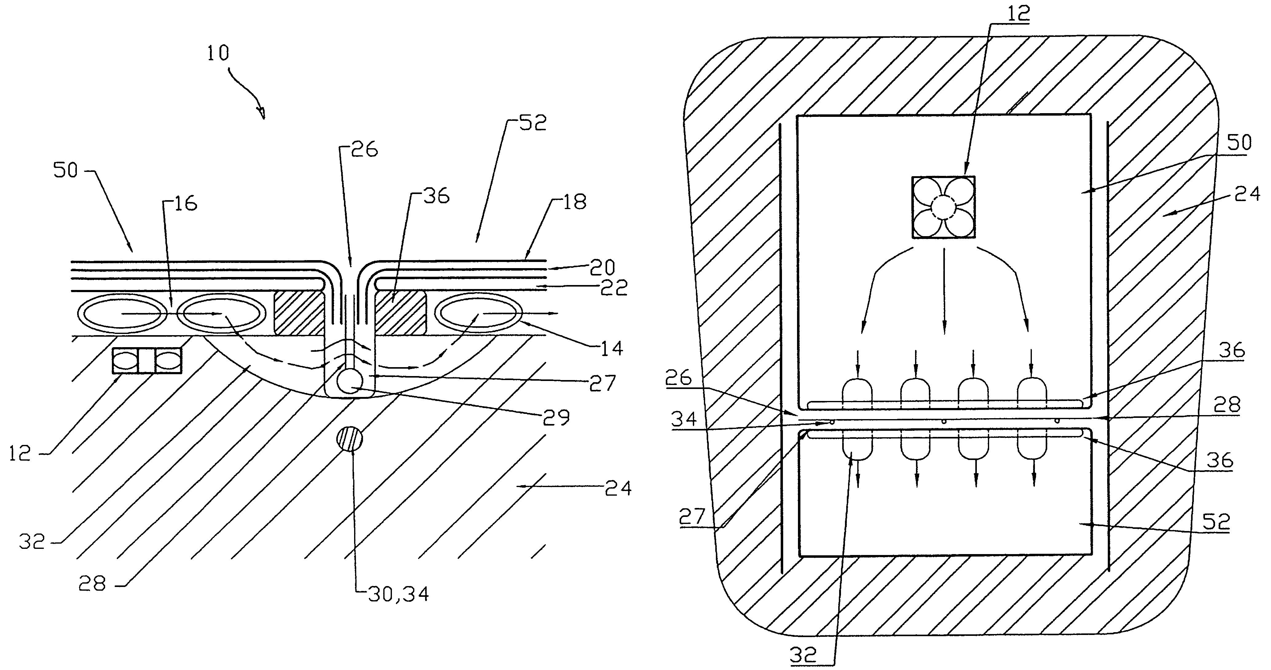
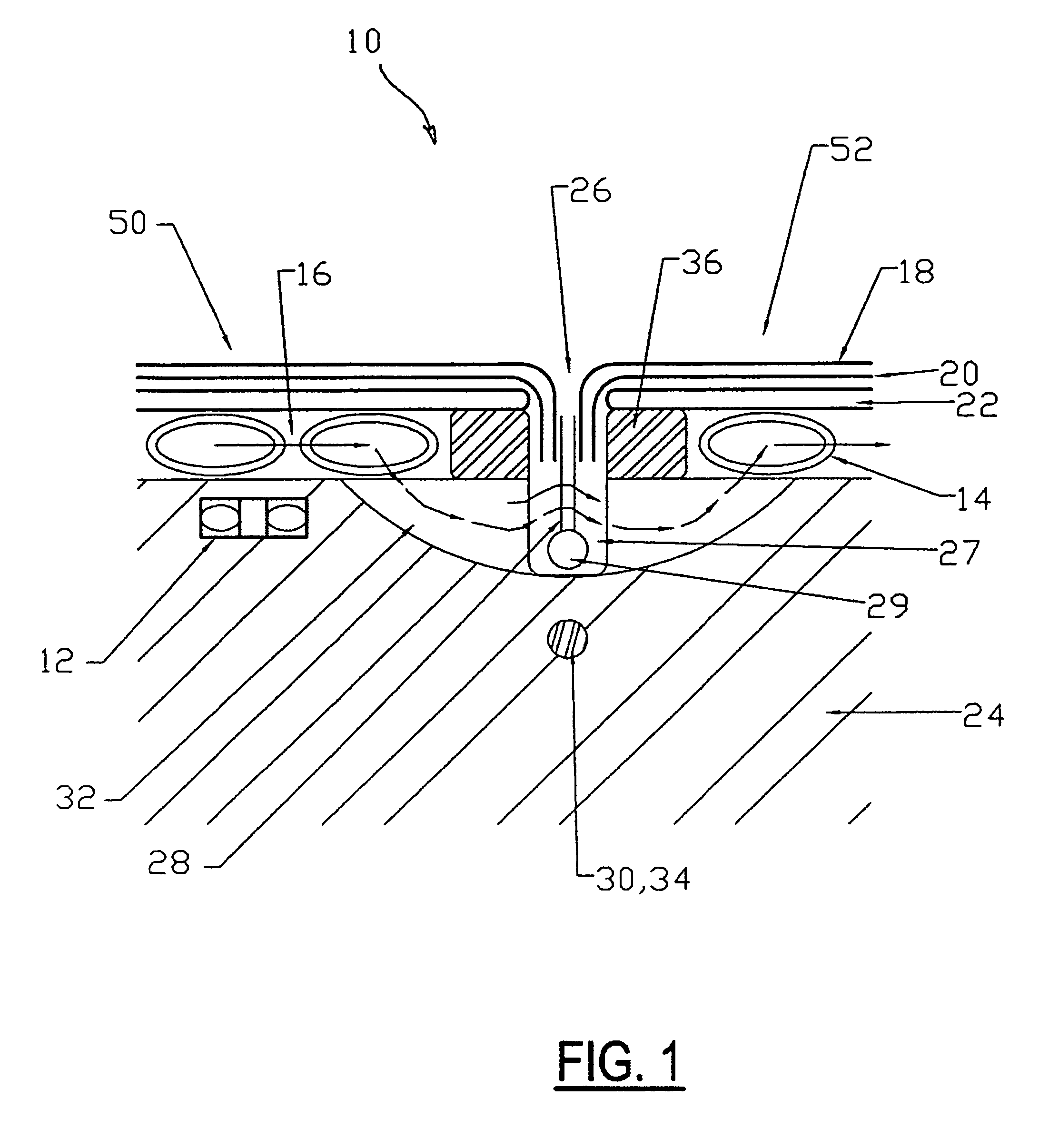
[0009]In another aspect, an air-conditioning mechanism for a seat, in particular a vehicle seat, provides that at least two air-conditioned zones of a seat and at least one depression located between the air-conditioned zones are connected together permeable to air by at least one connecting mechanism and that the at least one depression in the transverse direction, despite the cover, is at least partially passable by air. In addition, it is advantageous when the at least one connecting mechanism is located between the air-conditioned zones and the at least one depression, essentially on or above the floor level.
[0011]In a seat according to the present invention, a largely uniform supply of the air-circulating layers of various air-conditioned regions of the seat with air-conditioned air can be obtained without the depressions lying between them, which for example may be provided with stitchings, resulting in buildup or obstructions in air circulation. In this way, a cover furrow is produced which also ensures air circulation through the furrows into the next cover field.
[0015]Cover furrows according to the invention may be designed according to customers' specifications in their height profile and in their haptic properties. These properties are determined by the molded part placed on the cushion insert or on the cushion core. The entire arrangement is relatively simple to make. The steps for installation in the seat are simple and can be performed quickly. The passage of air between the air-conditioned zones of the seat separated by cover furrows, in particular when a plurality of connecting channels according to the invention are provided, is good enough that a single ventilation device, such as a blower located under the seat, suffices to ventilate all regions of the seat.

Problems solved by technology

In air-conditioned vehicle seats or other seating accommodations having air-circulating layers in the region of seat and / or backrest contact surfaces, the problem often arises in the case of stitched seat covers that the regions of a seat or backrest surface separated from one another by stitchings are unevenly air-conditioned, since the flow connection through the cover stitching furrow is insufficient.
In the current state of the art, implementation of cover stitching furrows through a ventilation layer of a knitted spacer fabric is not feasible, either visually or in terms of air-circulation technology.
Neither 90° angles nor smooth cushion edges can be formed using known spacer media, so that furrows and cover edges that are made using spacer media do not have a neat appearance.

Method used


Image

  • Air conditioning system for a seat
  • Air conditioning system for a seat
  • Air conditioning system for a seat

Examples


Embodiment Construction

[0020]In the following figures, the same reference numerals are used to refer to the same components. While the present invention is described as an air-conditioning system for use within a vehicle seat, it may be adapted and applied to various systems including other vehicle or non-vehicle systems requiring an air-conditioned surface. In this regard, in the following description, various operating parameters and components are described for several constructed embodiments. These specific parameters and components are included as examples only and are not meant to be limiting.

[0021]The schematic sectional view of FIG. 1 illustrates the structure of an air-conditioning system for a vehicle seat 10 according to an embodiment of the invention. A blower 12 delivers air into a distribution layer 14 through which air is able to flow. The distribution layer 14 has the task of distributing the air stream 16 through the entire cushion surface and an air-conditioned zone 50, 52 of the cushion...


PUM


Abstract

An air-conditioning system for a seat includes a cushion having a cover and two air-conditioned zones proximate a surface facing a seat occupant, and an elongated depression between the zones, the depression having a floor which is recessed with respect to the zones and into which the cover is at least partially drawn into in the direction of the depression floor, the air-conditioned zones being at least partially distanced from the depression. The zones and the depression are connected by a plurality of air-permeable channels, the channels being located between the air-conditioned zones essentially on or above the depression floor. The depression, in the transverse direction, is at least partially air-permeable, despite the cover.

Description

TECHNICAL FIELD[0001]The present invention relates to an air-conditioning mechanism for a seat, in particular for a vehicle seat.BACKGROUND OF THE INVENTION[0002]In air-conditioned vehicle seats or other seating accommodations having air-circulating layers in the region of seat and / or backrest contact surfaces, the problem often arises in the case of stitched seat covers that the regions of a seat or backrest surface separated from one another by stitchings are unevenly air-conditioned, since the flow connection through the cover stitching furrow is insufficient.[0003]In the current state of the art, implementation of cover stitching furrows through a ventilation layer of a knitted spacer fabric is not feasible, either visually or in terms of air-circulation technology. Neither 90° angles nor smooth cushion edges can be formed using known spacer media, so that furrows and cover edges that are made using spacer media do not have a neat appearance. A generally common procedure is to p...

Claims


Application Information

Patent Timeline
Patent Type & Authority Patents(United States)
IPC IPC(8): A47C7/72
CPCA47C7/74B60N2/5816B60N2/5621
Inventor STOEWE, STEFANULBRICH, THOMASHARNISCH, JENS
Owner GENTHERM GMBH
Learn More