
Cybernetic 3D music visualizer

a music visualization and 3d technology, applied in computing, electrophonic musical instruments, instruments, etc., can solve the problems of ineffective use of existing methods, all relatively limited in aesthetic possibilities, and used in real-tim

Inactive Publication Date: 2006-08-17
VASAN SRINI +2
View PDF7 Cites 77 Cited by
  • Summary
  • Abstract
  • Description
  • Claims
  • Application Information

AI Technical Summary

Benefits of technology

[0025] 7. Visual-ADSR. The method includes a configurable Visual Attack, Decay, Sustain and Release (‘V-ADSR’) transfer function applicable to any degree of freedom (feature vector) of 3D output parameters, enhancing even binary control inputs with continuous and aesthetic spatiotemporal symmetries of behavior.
[0026] 8. Symmetric Transfer Functions and Perceived Beauty. The method utilizes transfer functions providing multiple forms of applied symmetry in both passive (non-human-controlled) outputs as well as the human-controlled feedback processes. The multiple applications of symmetry increase the level of perceived visual harmony and beauty. Symmetry also enhances pattern recognition in control / feedback.

Problems solved by technology

These previous methods however, are all relatively limited in scope of aesthetic possibilities, and especially when employed in real-time, are limited to their music-synchronized effects being employed either in flat 2D or in a “pseudo-3D” or “2 1 / 2-D” environment.
This perception is however but an illusion and is limited, as in reality these visualizer methods are not functioning in a true 3D environment at all.
This lack may be quickly confirmed by the inability to arbitrarily and in real-time move camera position and viewpoint as is the case in a true 3D scene, as well as the inability to import arbitrary external 3D models into the scene and animate their parameters to music and player actions in real-time while retaining their full 3D characteristics, and the lack of such 3D capability as to choose amongst alternative texture maps and variously apply those to the 3D models in real-time.
However, compared with the potential richness of the MIDI message protocols, variety of message types and dynamic range, the available range of triggered results is relatively primitive and the protocol is not deeply exploited.
Applying MIDI triggers directly to 3D visual effects in real-time has either been severely limited in scope and flexibility due to limited system design, or when attempted is otherwise plagued by severe rendering latency issues which degrades the perceived synchronicity and thus also degrades the aesthetic result.
Visualizers which lack MIDI trigger as an option are even more severely hampered, as the alternatives of ASCII computer keyboard for example are limited by lack of velocity (i.e. are strictly binary) and typically limited to a maximum “polyphony” of two to four simultaneous triggers (keys) only.
For extended or complex media play the physical configurations of ASCII keyboards are also ergonomically undesirable and fatiguing.
While some visualizers do support MIDI input devices, their trigger-to-response feature set is so limited they do not exploit the potential for MIDI devices to overcome the limitations of ASCII keyboards.
Furthermore, the application of synchronization techniques between audio spectrum and / or MIDI live triggers to the visualizers' animation parameters have to date been lacking any functional equivalent to the technique widely used in audio synthesizers known as ADSR or Attack, Decay, Sustain and Release, whereby a relatively simply initial trigger, even a binary trigger, can be smoothed into a more aesthetic shape of response over time.
Furthermore, the previous visualizers' severe limits on scope of available simultaneous types of synchronization and extremely limited choices of visual parameters modulation have precluded the ability of multiple players and / or combinations of live players and audio to simultaneously co-exist in the multimedia result at all, or, when available to evidence a result of “visual cacophony” or confusion where distinct synchronization between each separate player, and / or between player(s) actions and audio modulation are not distinct feedback loops but a merged collective result.
These two prime requirements have been lacking in the field to date.
In addition, the current generation of music visualizers which are less intelligent, stand-alone and non-3D or only pseudo-3D-lookalikes, do not provide the capabilities of letting multiple users to simultaneously “jam” and co-create 3D architected scenes in real-time.
This severely limits the creativity of a group environment wherein the best of the best creative inputs are provided in real-time and a consensus based universal scenes could be orchestrated.
In addition, the current generation of visualizers have limitations because of the inefficiency of the manual manipulation of parameters through a large number of permutations and combinations a user is going to experiment with to create a set of new objects / scenes.

Method used


Image

  • Cybernetic 3D music visualizer
  • Cybernetic 3D music visualizer
  • Cybernetic 3D music visualizer

Examples


example # 1

Example #1 of Divided Control Ranges

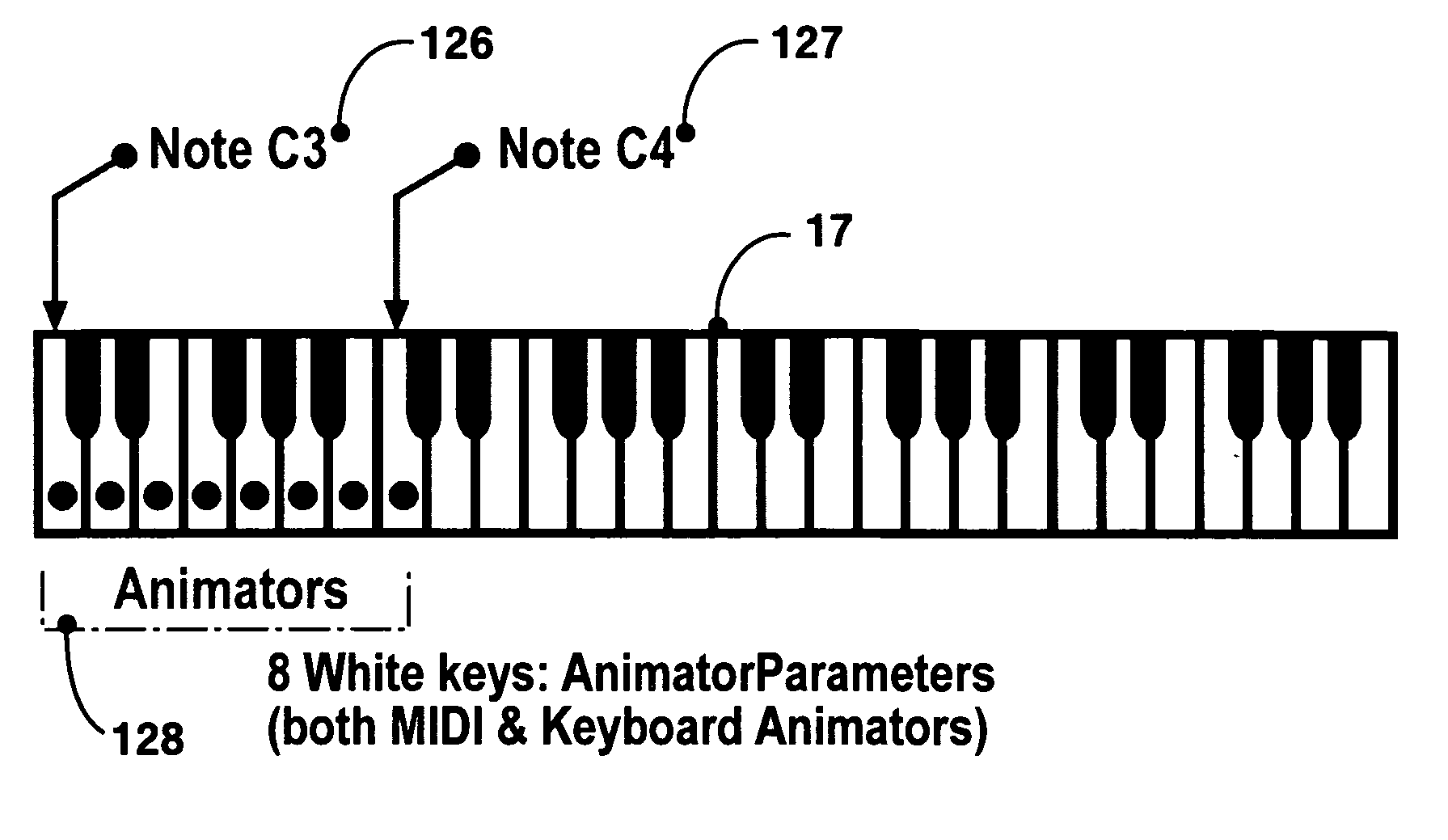
[0174]FIG. 14 illustrates an example of how to begin to divide up the control range for each the various sources, for say the first such Animator [95] one has in a Scene: What we show in FIG. 14 is: [0175] a. The Audio [20] coming through Winamp [7] has been reduced to a “slice” of the audio spectrum [112], by setting up a number of audio frequency “bins” and specifying which particular bin(s)' amplitude contributes towards a summed amplitude value to this Animator's output; (note: even frequency bin definition fields are animatable parameters); [0176] b. The internal Oscillators [17] have been setup in a way that only one of the four are contributing to the Animator's output [88] value, namely the first [113] or OSC1; [0177] c. The PC Keyboard [17] has been setup so that only one key, the Q key [114], will contribute to the Animator's output [88]; [0178] d. For MIDI [17] we're using (a MIDI piano keyboard's) Note ON Message Type, and we've limit...

example # 2

Example #2 of Divided Control Ranges

[0182]FIG. 15 illustrates an example of how to divide up the control range for the various sources, for say the Animator #2 [125] in the Scene, and to clearly distinguish its contribution from that of the first Animator.

[0183] What we show in FIG. 15, as contrasted from the FIG. 14“Animator #1” example, is: [0184] a. The Audio [20] coming through Winamp [7] has been reduced to a different “slice” of [116] the audio spectrum, by setting up a number of audio “bins” and specifying which particular bin(s) contributes a value to this Animator's output [88], to cover a different audio frequency range as compared to that of the Animator #1 setup; [0185] b. The internal Oscillators [17] have been setup in a way that only one of the four are contributing to the Animator #2[125] output value, namely the second [117] or OSC2; [0186] c. The PC Keyboard [17] has been setup so that only one key, the W key [118], will contribute to the Animator #2 [125] output...


PUM


Abstract

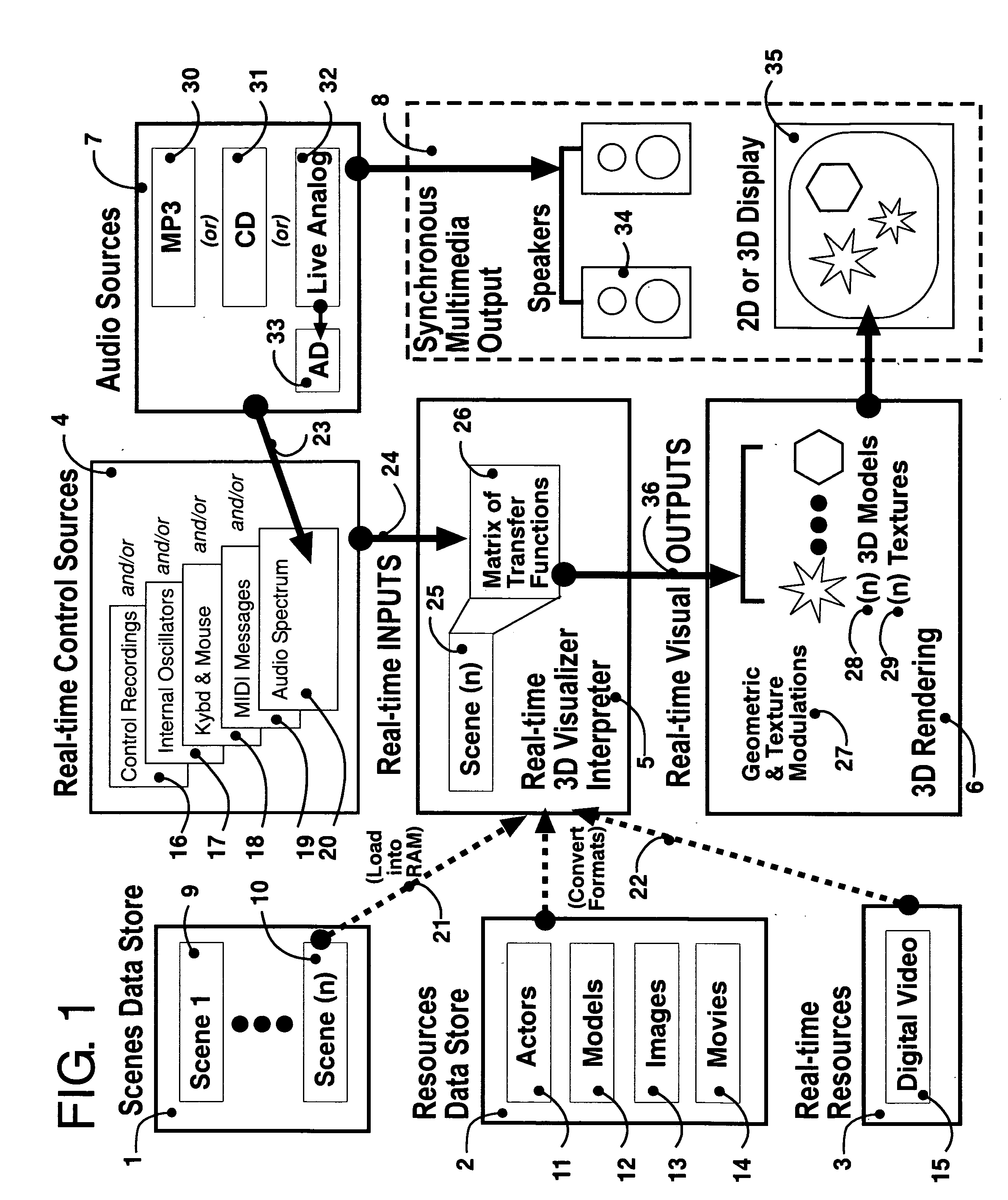
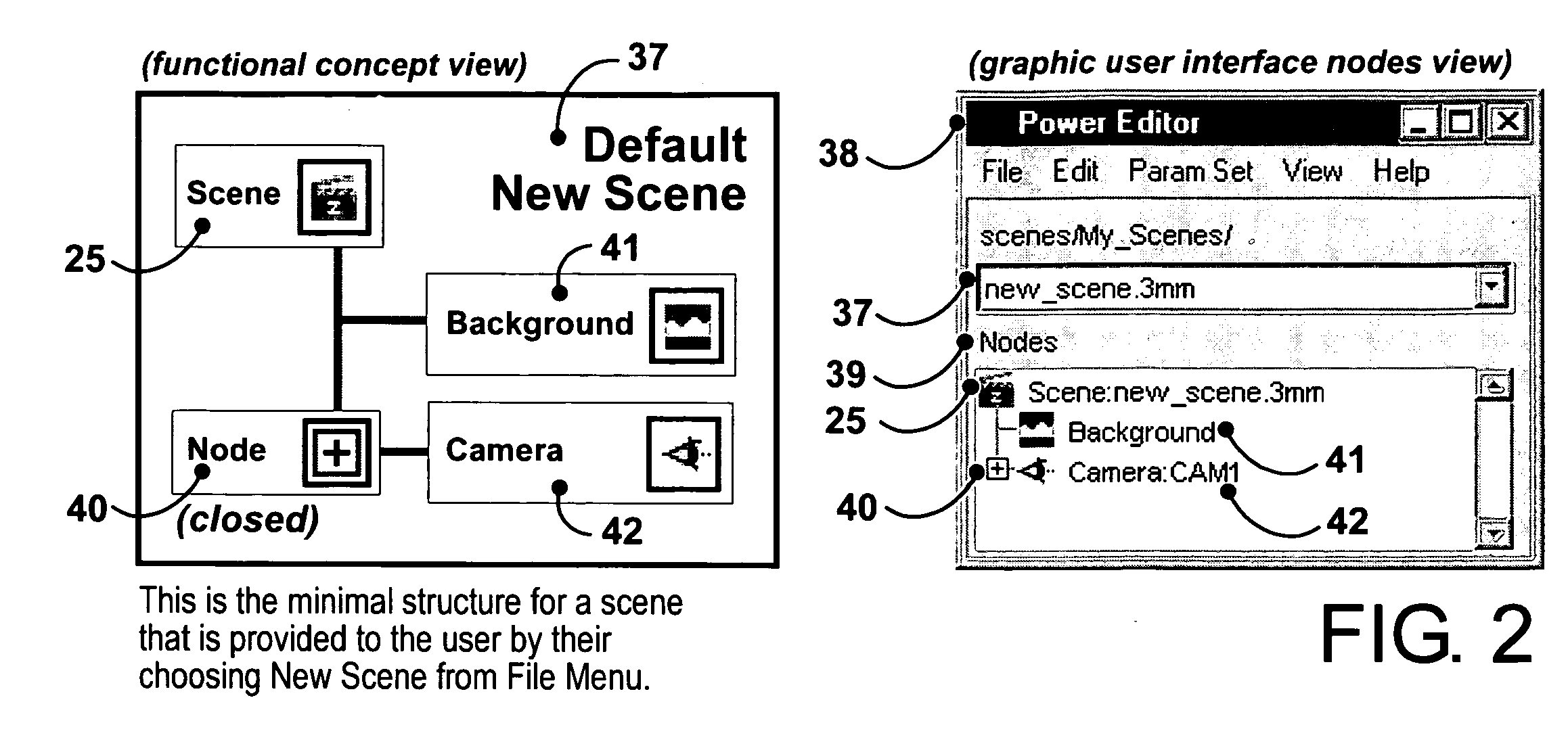
3D music visualization process employing a novel method of real-time reconfigurable control of 3D geometry and texture, employing blended control combinations of software oscillators, computer keyboard and mouse, audio spectrum, control recordings and MIDI protocol. The method includes a programmable visual attack, decay, sustain and release (V-ADSR) transfer function applicable to all degrees of freedom of 3D output parameters, enhancing even binary control inputs with continuous and aesthetic spatio-temporal symmetries of behavior. A “Scene Nodes Graph” for authoring content acts as a hierarchical, object-oriented graphical interpreter for defining 3D models and their textures, as well as flexibly defining how the control source blend(s) are connected or “Routed” to those objects. An “Auto-Builder” simplifies Scene construction by auto-inserting and auto-routing Scene Objects. The Scene Nodes Graph also includes means for real-time modification of the control scheme structure itself, and supports direct real-time keyboard / mouse adjustment to all parameters of all input control sources and all output objects. Dynamic control schemes are also supported such as control sources modifying the Routing and parameters of other control sources. Auto-scene-creator feature allows automatic scene creation by exploiting the maximum threshold of visualizer set of variables to create a nearly infinite set of scenes. A Realtime-Network-Updater feature allows multiple local and / or remote users to simultaneously co-create scenes in real-time and effect the changes in a networked community environment where in universal variables are interactively updated in real-time thus enabling scene co-creation in a global environment. In terms of the human subjective perception, the method creates, enhances and amplifies multiple forms of both passive and interactive synesthesia. The method utilizes transfer functions providing multiple forms of applied symmetry in the control feedback process yielding an increased level of perceived visual harmony and beauty. The method enables a substantially increased number of both passive and human-interactive interpenetrating control / feedback processes that may be simultaneously employed within the same audio-visual perceptual space, while maintaining distinct recognition of each, and reducing the threshold of human ergonomic effort required to distinguish them even when so coexistent. Taken together, these novel features of the invention can be employed (by means of considered Scene content construction) to realize an increased density of “orthogonal features” in cybernetic multimedia content. This furthermore increases the maximum number of human players who can simultaneously participate in shared interactive music visualization content while each still retaining relatively clear perception of their own control / feedback parameters.

Description

REFERENCES [0001] (1) U.S. Pat. No. 6,395,969 May 28, 2002 Fuher, John Valentin “System and method for artistically integrating music and visual effects”[0002] (2) US Patent Application #20050188012 Aug. 25, 2005 Dideriksen, Tedd “Methods and Systems for synchronizing visualizations with audio streams”FIELD OF THE INVENTION [0003] The present invention relates to a real-time 3D music visualization engine for creating, storing, organizing, and displaying a vast scope of music-synchronized 3D visual effects in a true interactive 3D space for use in production of pre-recorded multimedia content as well as for live interactive multimedia performances. BACKGROUND OF THE INVENTION [0004] For some decades a variety visual media production methods have been employed to enhance the enjoyment and increase the perceptual impact of musical content. These have ranged from simple sequences of time synchronized still images, to precisely timely lighting systems, to carefully composed video content...

Claims


Application Information

Patent Timeline
Patent Type & Authority Applications(United States)
IPC IPC(8): G06T15/70
CPCG06T13/20G10H1/0008G10H2220/005G10H2240/311
Inventor VASAN, SRINIHENDERSON, RIKBULATOV, VLADIMIR
Owner VASAN SRINI
Learn More