
Liquid crystal on silicon (LCOS) display driving system and the method thereof

a technology of liquid crystal on silicon and driving system, applied in the direction of television system, color television details, instruments, etc., can solve the problems of significant increase in the manufacturing cost and complexity of the lcos display driving system, incorrect r data level, erroneous display of r, g and b data, etc., and achieve the effect of minimizing the coupling

Active Publication Date: 2006-08-10
HIMAX TECH LTD
View PDF2 Cites 33 Cited by
  • Summary
  • Abstract
  • Description
  • Claims
  • Application Information

AI Technical Summary

Benefits of technology

The present invention provides a LCOS display driving system and method that can minimize the coupling effect and clock feedthrough effect, which can lead to more accurate and efficient display of data. This is achieved by generating a control code for a loading sequence of R, G, and B data for pixels in one of scan lines, multiplexing the data according to the control code, shifting the levels of the data, converting the data to a corresponding analog data, and demultiplexing the data according to the control code. Overall, this invention allows for more accurate and efficient display of data on LCOS displays.

Problems solved by technology

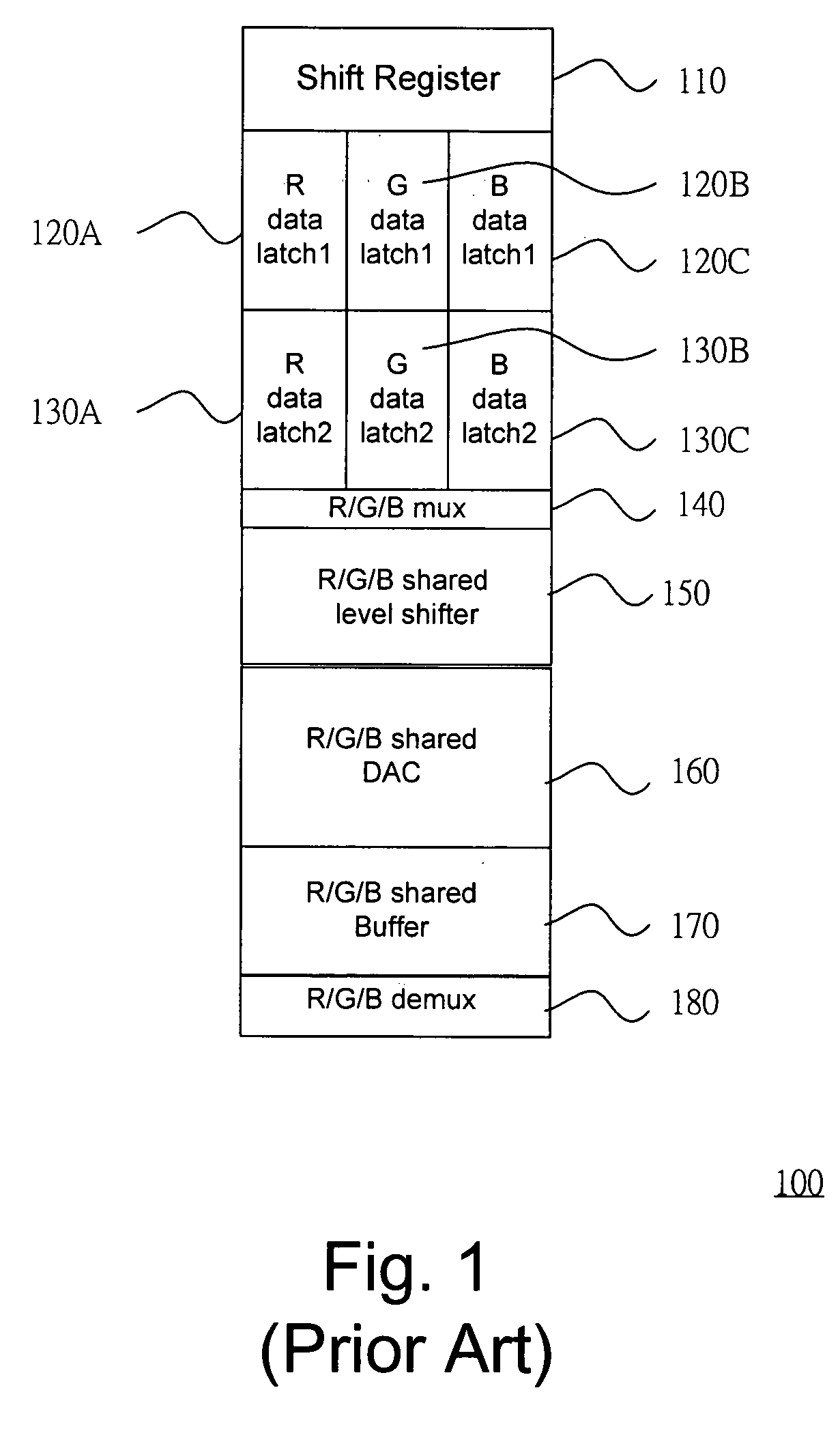
This architecture significantly increases the manufacturing cost and complexity of the LCOS display driving system.
However, while the R, G, and B data are loaded in this sequential pattern, a so-called “data line floating” effect will arise, and dramatically interfere with the adjacent data, resulting in an erroneous display. FIG. 3 is a timing chart illustrating the “data line floating” effect while the R, G, and B data are loaded in a sequential pattern.
The loading of G and B data both couples to the previously loaded R data, resulting in an incorrect R data level.
These coupling effects between the R, G, and B data in a scan line will lead to an erroneous display of the R, G, and B data.
Besides, during the demultiplexing, a clock feed-through effect will also cause a faulty display. FIG. 4 shows a circuit diagram in the demultiplexer 180.

Method used


Image

  • Liquid crystal on silicon (LCOS) display driving system and the method thereof
  • Liquid crystal on silicon (LCOS) display driving system and the method thereof
  • Liquid crystal on silicon (LCOS) display driving system and the method thereof

Examples


Embodiment Construction

[0033] Reference will now be made in detail to the present preferred embodiments of the invention, examples of which are illustrated in the accompanying drawings. Wherever possible, the same reference numbers are used in the drawings and the description to refer to the same or like parts.

[0034] The LCOS display driving system according to the present invention employs a non-sequential pattern for loading the R, G, and B data to pixels in each scan line that the coupling effecting between loaded data can be minimized. Besides, the LCOS display driving system according to the present invention further utilizes a data compensation block for compensating the clock feedthrough effect during the demulplexing.

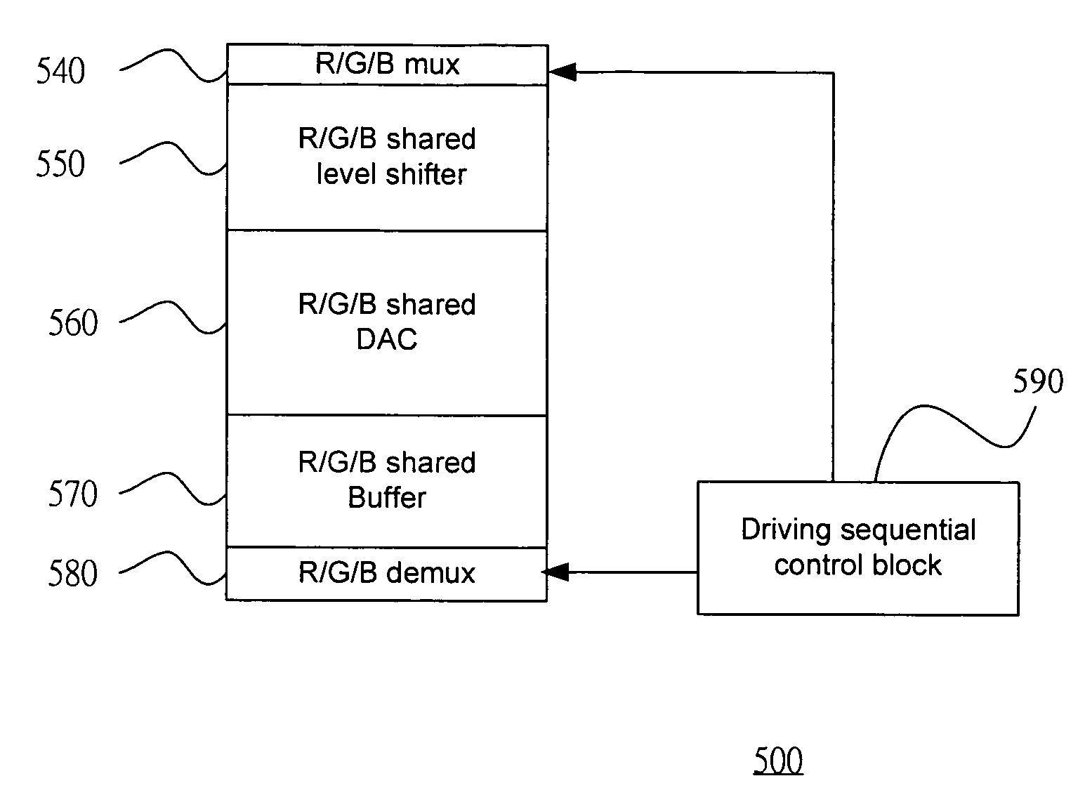
[0035]FIG. 5 is a block diagram illustrating the LCOS display driving system according to the present invention. The LCOS display driving system 500 comprises a multiplexer 540, a shared level shifter 550, a shared DAC 560, a shared unity-gain buffer 570, a demultiplexer 580, and a ...


PUM


Abstract

The present invention relates to a LCOS display driving system. The driving sequential control block generates a control code representing a loading sequence of the R, G, and B data for pixels in one of scan lines. The multiplexer multiplexes the R, G, and B data from latches according the control code. The shared level shifter shifts the level of the R, G, and B data from the multiplexer. The digital analog converts converting the R, G, and B data to a corresponding analog R, G, and B data voltage. The shared unity-gain buffer stores the analog R, G, and B data voltage from the shared digital analog converter. The demultiplexer demultiplexes the analog R, G, and B data voltage according the control code.

Description

BACKGROUND [0001] 1. Field of Invention [0002] The present invention relates to a LCOS (Liquid Crystal On Silicon) display field. More particularly, the present invention relates to a color LCOS display loading the R, G, and B data in a non-sequential pattern. [0003] 2. Description of Related Art [0004] In a conventional color LCOS display driving system, a driving set of a level shifter, a Digital Analog Converter (DAC), and a unity-gain buffer is required for each R, G, and B data supplied to a pixel. Therefore, for example, if there are 80 pixels in a scan line, driving sets with total number of 240 may be required. This architecture significantly increases the manufacturing cost and complexity of the LCOS display driving system. [0005] Recently, a color LCOS display driving system with shared components, such as a shared level shifter, a shared DAC, and a shared unity-gain buffer for all R, G, and B data supplied to a pixel is proposed. This type of LCOS display driving system e...

Claims


Application Information

Patent Timeline
Patent Type & Authority Applications(United States)
IPC IPC(8): G09G3/36
CPCG09G3/3688G09G2310/027G09G2310/0297G09G2320/0209
Inventor YEN, CHENG-CHILEO, HON-YUANHO, YUNG-YUANCHEN, YEN-CHEN
Owner HIMAX TECH LTD
Learn More