
Electric field detector

a detector and electric field technology, applied in the direction of electromagentic field characteristics, instruments, measurement devices, etc., can solve the problems of prone to stray capacitive coupling to other bodies, false readings, etc., and achieve the effect of enhancing certain desirable characteristics of free body electric field detectors

Inactive Publication Date: 2009-02-05
TRETHEWEY MARK
View PDF3 Cites 1 Cited by
  • Summary
  • Abstract
  • Description
  • Claims
  • Application Information

AI Technical Summary

Benefits of technology

[0012]It is the aim of the present invention to eliminate or at least minimise the foregoing disadvantages and also to enhance certain desirable characteristics of free body electric field detectors.
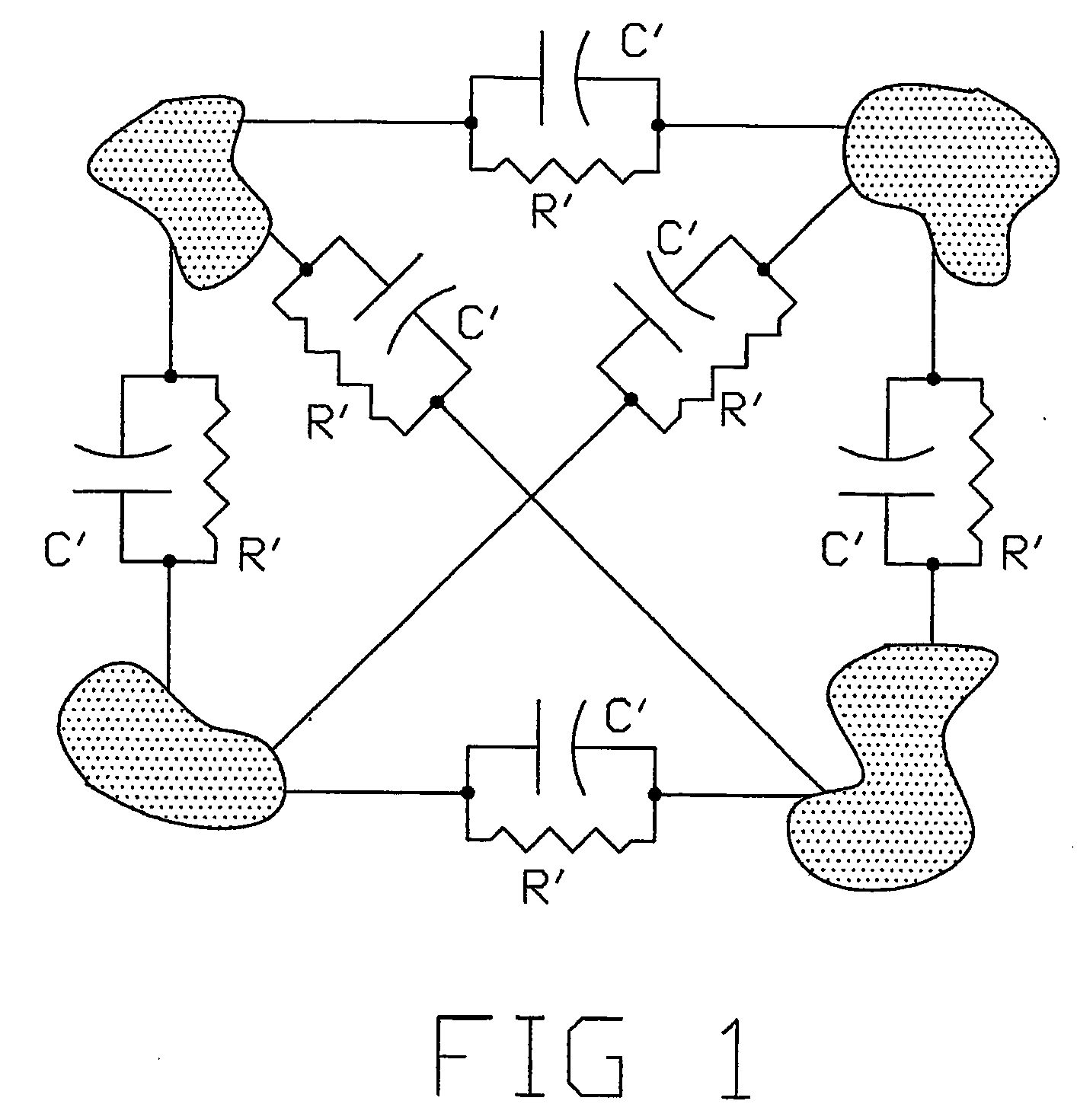
[0018]Secondly, if the intrinsic capacitance of the detector is large in relation to the coupling capacitance, then the effect of the coupling capacitance is minimised. This occurs because the coupling capacitance can now only make a small percentage change in the total detector capacitance.
[0020]However, ferrites have some interesting properties in this regard. Most ferrites are relatively poor conductors and allow electric fields to penetrate into their internal volumes, hence minimizing the Faraday shield effect and allowing the sensor to detect electric field in a space volume. Preexisting designs only detected electric field over the surface area of the detector.
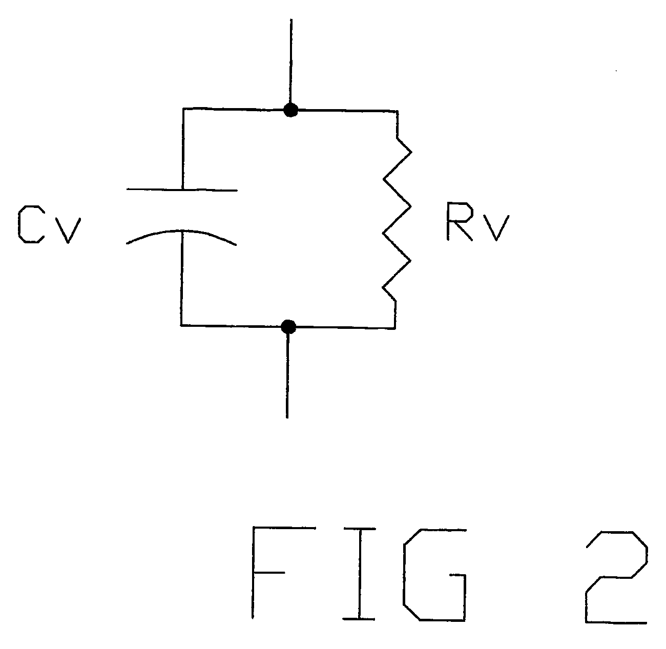
[0026]The volume resistivity of the ferrite and the increased inductance of the assembly damps the sensor capacitance, improving output stability and discriminating high frequency noise.

Problems solved by technology

Due to the large surface areas of these detectors they are very prone to stray capacitive coupling to other bodies in their proximity.
So any modification of detector capacitance by stray capacitive coupling will modify the detector output, thus giving false readings.

Method used


Image

  • Electric field detector
  • Electric field detector
  • Electric field detector

Examples


Embodiment Construction

[0035]One preferred form of the invention will now be described by way of example, notwithstanding any other forms that may fall within the scope of the invention.

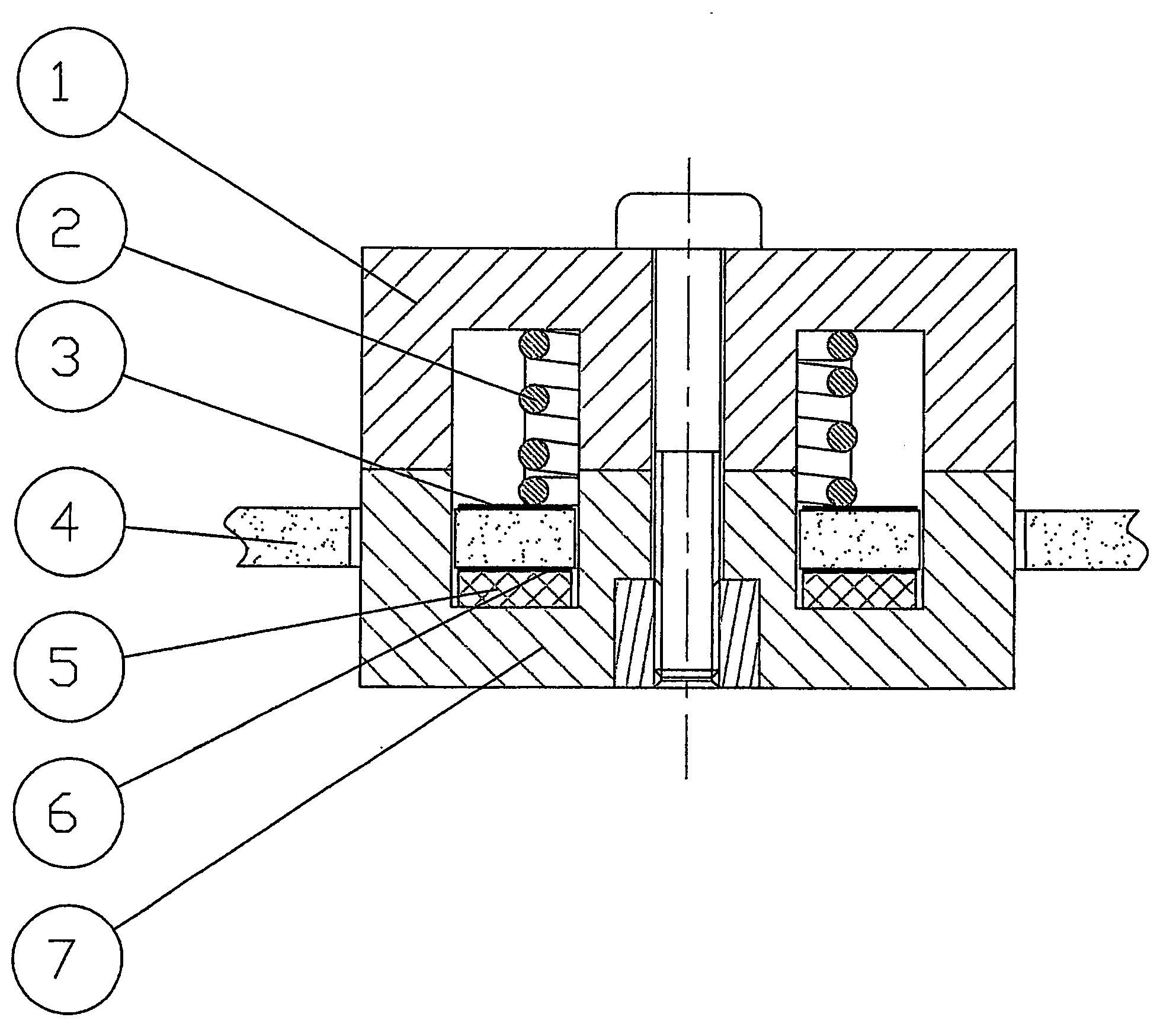
[0036]Referring to FIGS. 5 and 6, the sensor consists of an upper ferrite pole piece (1), a lower ferrite pole piece (7), an insulation washer (5), contact spring (2), fiberglass board (4) and copper sheets (3) and (6).

[0037]The sensor is designed to be an integral part of a printed circuit board, with the fiberglass board (4) being the basic substrate of the printed circuit board. The copper sheets (3) and (6) are specially shaped sections of track on the top and bottom sides of the printed circuit board. The printed circuit board has holes (8) routed in it to allow the lower ferrite pole piece (7) to fit up through it. The copper sheets (3) and (6) are etched so they have a small clearance between their edges and the walls of the lower ferrite pole piece (7), thus ensuring they remain insulated.

[0038]The copper sheets (3...


PUM


Abstract

The detector utilises the microstructure and effects integration of an electric field over the volume of a ferrite core. The detector, in one form, includes upper ferrite pole half (1), lower ferrite pole half (7), circuit board (4), insulating washer (5) and spring conductor (2). Assembled, between the ferrite halves (1 and 7) is the spring conductor (2) compressed against the upper ferrite (1) and the circuit board (4) with the washer (5) between the circuit board (4) and the lower ferrite (7). There are two conducting plates (3), either side of the circuit board (4), a first insulated from the lower ferrite (7) by the washer (5) and the second in electrical contact with the upper ferrite (1) via spring conductor (2). A voltage produced across the plates (4) is related to the detected electric field.

Description

BACKGROUND[0001]In the past, time harmonic electric fields were detected using free-body electric field meters. These detectors were typically of spherical or cubic geometry and were constructed from conductive material. When placed in a time harmonic electric field a charge will oscillate between two electrically isolated halves of the detector. Mathematically this charge can be described by:Q=A·εo·E Where:[0002]εo=permittivity of free space[0003]E=electric field strength to be detected[0004]A=a constant proportional to detector surface area[0005]Q=charge on detector[0006]To achieve useful detector sensitivity the detector dimensions are typically in the order of 10 cm (4 inches.)[0007]Due to the large surface areas of these detectors they are very prone to stray capacitive coupling to other bodies in their proximity. This can modify the capacitance of the detector assembly, and the above equation can be re-arranged to:Q=C·d·E Where:[0008]C=total capacitance of detector[0009]d=spac...

Claims


Application Information

Patent Timeline
IPC IPC(8): G01R29/08G01D5/24
CPCG01D5/24
Inventor TRETHEWEY, MARK
Owner TRETHEWEY MARK
Learn More