
Electric field detector

a detector and electric field technology, applied in the field of electric field detectors, can solve the problems of prone to stray capacitive coupling to other bodies, false readings, etc., and achieve the effect of enhancing certain desirable characteristics of free body electric field detectors

Inactive Publication Date: 2006-08-24
TRETHEWEY MARK
View PDF0 Cites 6 Cited by
  • Summary
  • Abstract
  • Description
  • Claims
  • Application Information

AI Technical Summary

Benefits of technology

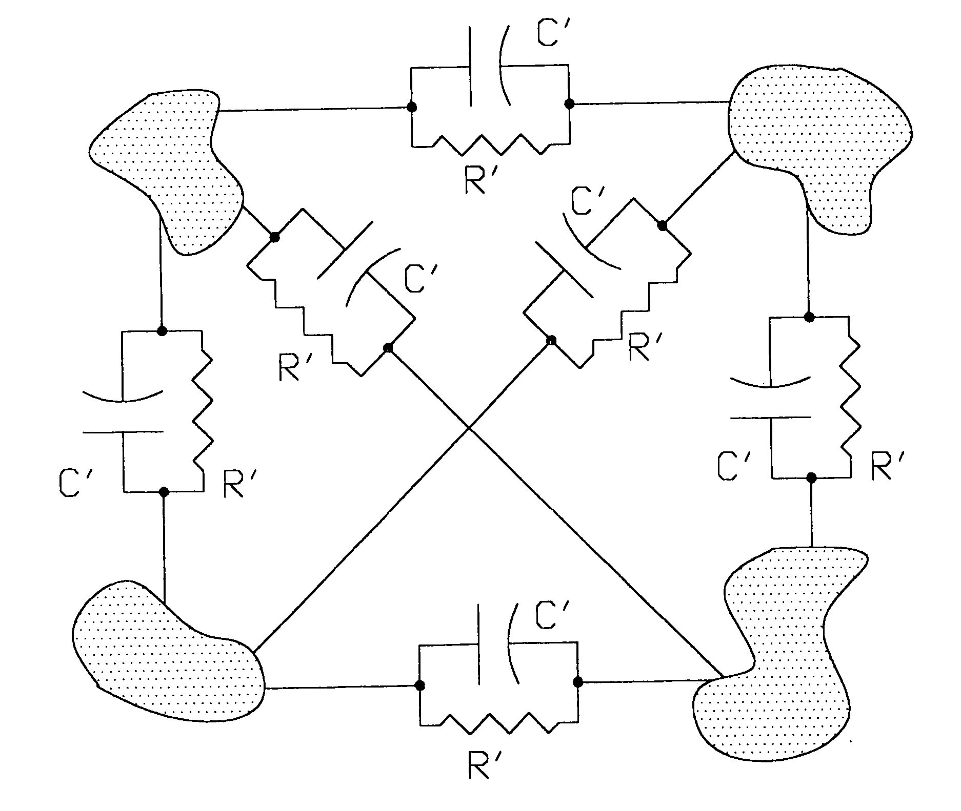
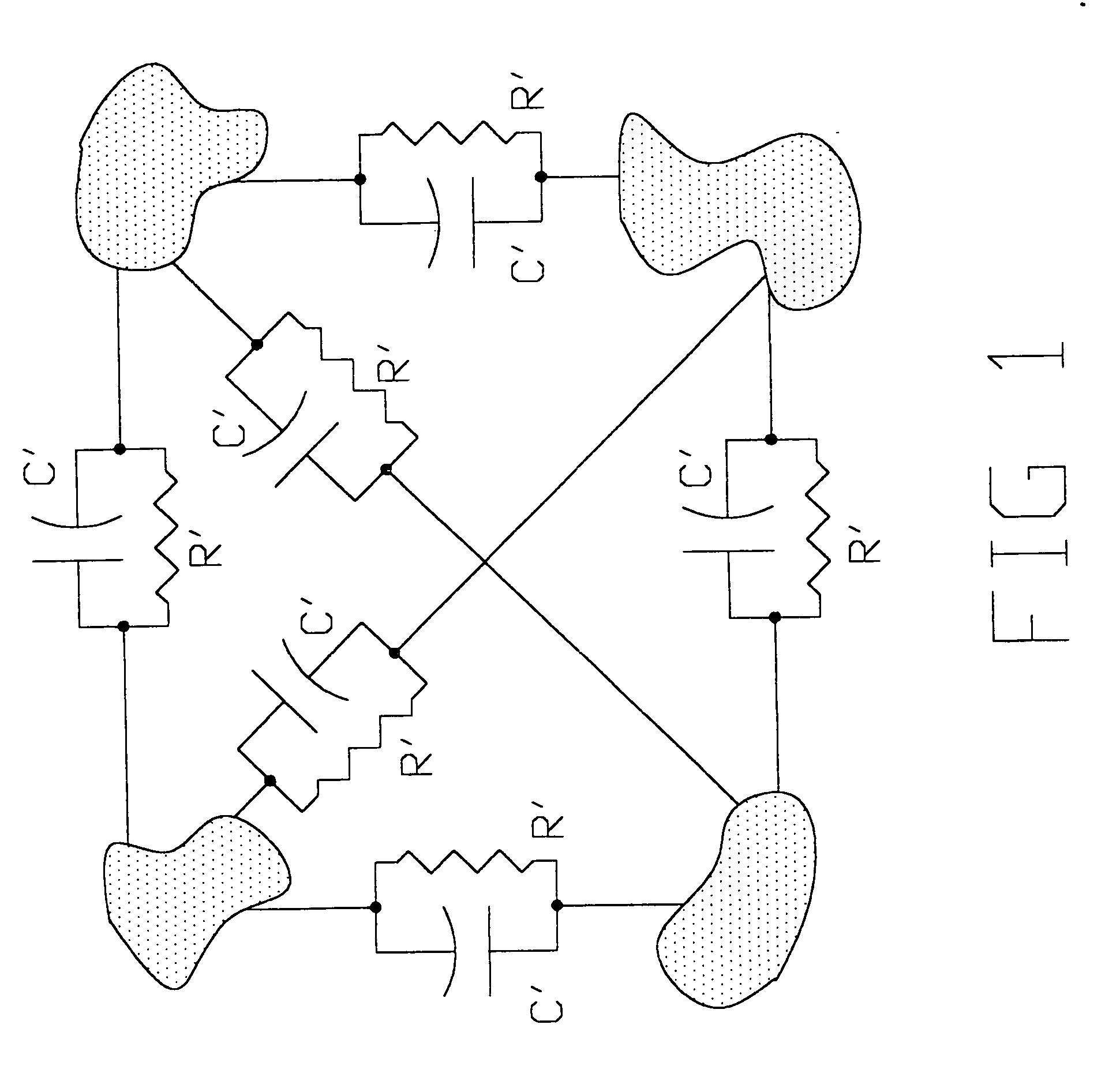
The present invention aims to improve the performance of free body electric field detectors by eliminating or minimizing certain disadvantages and enhancing desirable characteristics. The invention proposes a method to increase the detector's capacitance by adding a stable capacitance to it. This is achieved by reducing the area of the detector and the coupling capacitance. The invention also suggests using ferrites, which have volume resistivity and volume capacitance, to detect electric fields in a space volume. The use of fiberglass and suitable electronics can improve the detector's output stability and discrimination of stray effects. Overall, the invention provides a solution to enhance the performance of free body electric field detectors.

Problems solved by technology

Due to the large surface areas of these detectors they are very prone to stray capacitive coupling to other bodies in their proximity.
So any modification of detector capacitance by stray capacitive coupling will modify the detector output, thus giving false readings.

Method used


Image

  • Electric field detector
  • Electric field detector
  • Electric field detector

Examples


Embodiment Construction

[0038] One preferred form of the invention will now be described by way of example, notwithstanding any other forms that may fall within the scope of the invention.

[0039] Referring to FIGS. 5 and 6, the sensor consists of an upper ferrite pole piece (1), a lower ferrite pole piece (7), an insulation washer (5), contact spring (2), fiberglass board (4) and copper sheets (3) and (6).

[0040] The sensor is designed to be an integral part of a printed circuit board, with the fiberglass board (4) being the basic substrate of the printed circuit board. The copper sheets (3) and (6) are specially shaped sections of track on the top and bottom sides of the printed circuit board. The printed circuit board has holes (8) routed in it to allow the lower ferrite pole piece (7) to fit up through it. The copper sheets (3) and (6) are etched so they have a small clearance between their edges and the walls of the lower ferrite pole piece (7), thus ensuring they remain insulated.

[0041] The copper sh...


PUM


Abstract

The present invention relates to an improved method to detect electric field intensity. It is a generational improvement on free body field detectors and uses a ferrite sensor element to increase detector capacitance and hence signal output. This configuration also provides reduced detector volume, increased stability and a reduction in susceptibility to capacitive coupling. This system provides an output signal proportional to the electric field strength integrated over the volume of the ferrite detector element. Further this system is low cost and passive. A passive system uses no supply power and does not suffer from increased noise floor characteristics like active devices.

Description

BACKGROUND [0001] In the past, time harmonic electric fields were detected using free-body electric field meters. These detectors were typically of spherical or cubic geometry and were constructed from conductive material. When placed in a time harmonic electric field a charge will oscillate between two electrically isolated halves of the detector. Mathematically this charge can be described by: Q=A·εo·E [0002] Where: εo=permittivity of free space [0003] E=electric field strength to be detected [0004] A=a constant proportional to detector surface area [0005] Q=charge on detector [0006] To achieve useful detector sensitivity the detector dimensions are typically in the order of 10 cm (4 inches.) [0007] Due to the large surface areas of these detectors they are very prone to stray capacitive coupling to other bodies in their proximity. This can modify the capacitance of the detector assembly, and the above equation can be re-arranged to: Q=C·d·E [0008] Where: C=total capacitance of de...

Claims


Application Information

Patent Timeline
Patent Type & Authority Applications(United States)
IPC IPC(8): G01R31/00
CPCG01R29/12
Inventor TRETHEWEY, MARK
Owner TRETHEWEY MARK
Learn More