
Wire for inserting into biological duct

Inactive Publication Date: 2006-08-03
NIHON UNIVERSITY
View PDF6 Cites 2 Cited by
  • Summary
  • Abstract
  • Description
  • Claims
  • Application Information

AI Technical Summary

Benefits of technology

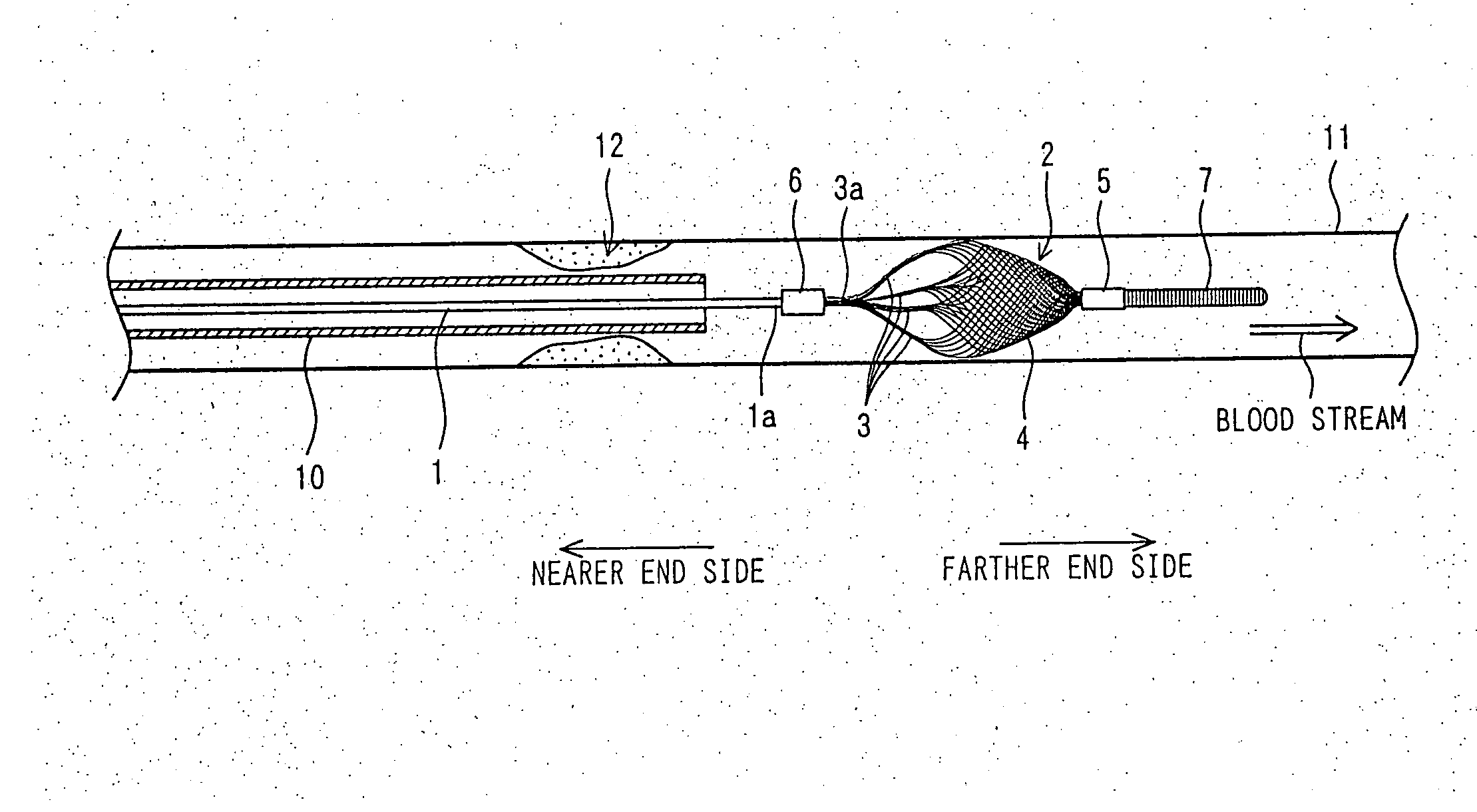
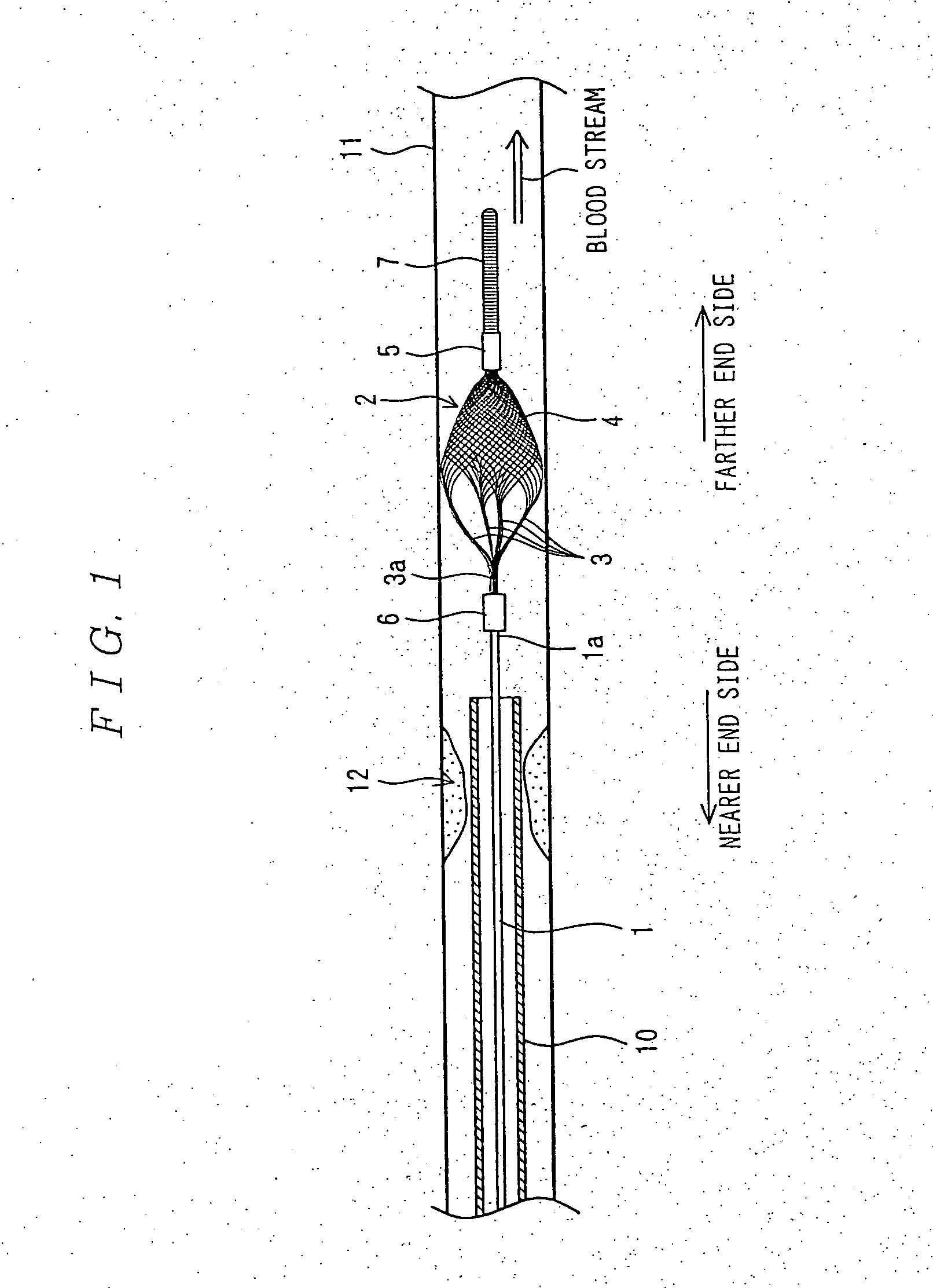
[0010] According to the invention, by configuring the filter body of a meshed material, obstruction of the stream within the intravital tract is avoided.
[0012] Furthermore, the presence of the elastic force to form the aforementioned shape, no other mechanism to achieve swelling into the intended shape is needed, and the configuration is correspondingly simplified to make possible more compact folding.
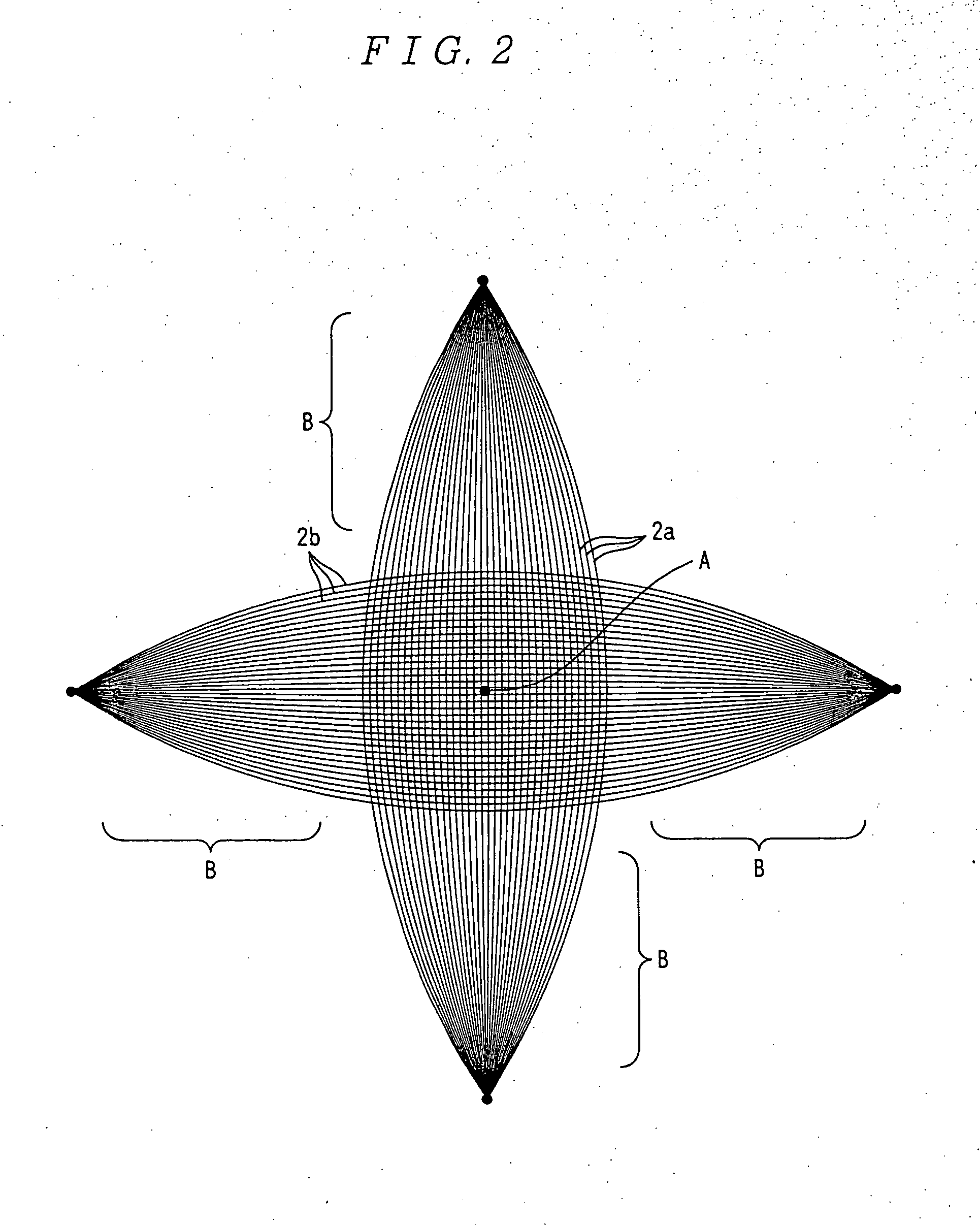
[0014] Since the stream of fluid in a tract is the highest in flow rate in the central part of the tract, embolic material floating in the fluid is captured, first from the concave central position of the filter body consisting of a meshed material. Therefore, by setting the meshes of the concave central position of the filter body smaller than anywhere else as according to the invention under the present application, the stream of the fluid can be more easily ensured by the meshes of the outer circumference of the filter while securely capturing small pieces of embolic material.
[0017] The composition using a shape-memory alloy makes more secure restorability of the originally intended shape even after staying in a folded state for a long time.
[0022] The presence of the guide wire facilitates guidance of the capture filter swelling in the radial direction along the intravital tract.

Problems solved by technology

Where a blood vessel is to be so treated, these pieces of the removed substance will be carried by the blood flow and may block thinner blood vessels downstream.
However, in the wire for insertion into intravital tracts, as the umbrella-shaped cover consisting of a membrane constitute the filter to capture embolic material, there is a fear that the umbrella-shaped cover itself may obstruct blood circulation in the blood vessel.
There is a version in which many holes are bored in that membrane, but this still involves a fear of failure to ensure a sufficient blood stream.
Further, to consider a state in which capture filter is folded, the diameter of the capture filter will be increased by the thickness of the membrane doubled by the folding, and the filter will become correspondingly less adaptive to thin tracts.

Method used


Image

  • Wire for inserting into biological duct
  • Wire for inserting into biological duct
  • Wire for inserting into biological duct

Examples


embodiment

[0067] An embodiment was configured of a capture filter 2 having a maximum expansible diameter of 8 mm and a filter body 4 consisting of 72 filaments. In this case, the diameter and mesh size of the expanded filter body 4 theoretically has a relationship shown in FIG. 3. The mesh opening sizes in the drawing are given in terms of diameters in the opening sectional areas converted into circular areas.

[0068] And a wire for intravital insertion equipped with the capture filter was arranged in a glass tube of 5.8 mm in bore, instead of a blood vessel, and a capture experiment was carried out. Incidentally, the maximum mesh size in this experiment was 0.25 mm.

[0069] And, while circulating water in the glass tube at a flow rate equivalent to the blood stream, polyvinyl alcohol (PVA) of 100 to 200 micrometers in grain size was let flow, and the weight of the PVA particles which were not captured and passed the filter was measured for evaluation.

[0070] As a result of the evaluation, it w...


PUM


Abstract

A wire for insertion into intravital tracts applicable even to small-diameter tracts while securing the stream in the tract is to be provided. A capture filter 2 is disposed at the tip of a principal wire 1 consisting of steel filaments. The capture filter 2 is configured of four support wires 3 and a basket-shaped filter body 4 consisting of a meshed material. The filaments constituting the support wires 3 and those constituting the filter body 4 are integrally formed and consist of a superelastic alloy.

Description

TECHNICAL FIELD [0001] The present invention relates to a wire for insertion into intravital tracts provided with a capture filter to be temporarily arranged in an intravital tract, such as a blood vessel, to capture embolic material or the like in the tract. BACKGROUND ART [0002] In many cases of treating a lesion in an intravital tract, such as removing cholesterol or anything else that has accumulated in a blood vessel or removing gallstones in the gall duct, the substance concerned is removed from the wall surface of the tract. Where a blood vessel is to be so treated, these pieces of the removed substance will be carried by the blood flow and may block thinner blood vessels downstream. [0003] According to a technique to address this problem disclosed in JP2001-212152A (hereinafter referred to as Patent Reference 1), a filter is temporarily arranged in the tract by inserting a wire provided with a capture filter, and such potentially embolic material is captured by the filter. [...

Claims


Application Information

Patent Timeline
IPC IPC(8): A61M29/00A61B17/00A61F2/01
CPCA61B2017/00287A61B2017/00867A61F2/013A61F2002/016A61F2002/018A61F2230/0006A61F2230/008
Inventor SAITO, SATOSHIKAWABE, DAISUKE
Owner NIHON UNIVERSITY
Learn More