
Adaptive electro-active lens with variable focal length

Active Publication Date: 2006-07-27
JOHNSON & JOHNSON VISION CARE INC
View PDF77 Cites 257 Cited by
  • Summary
  • Abstract
  • Description
  • Claims
  • Application Information

AI Technical Summary

Benefits of technology

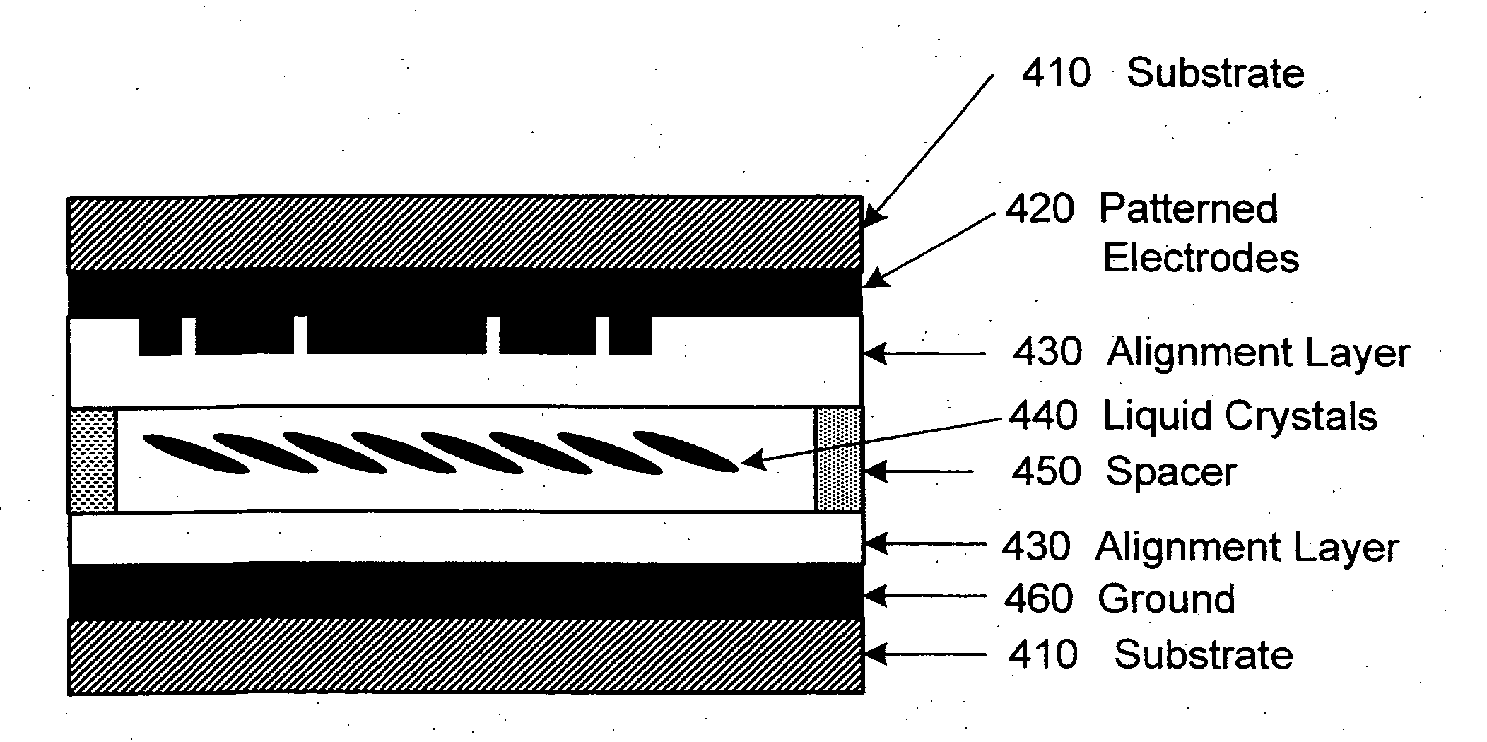
[0007] More specifically, provided is an adjustable focusing electrically controllable electroactive lens. Also provided are methods for discretely or continuously adjusting the focal length of an electrically controllable electroactive lens. Electrically controllable electroactive lenses allow the focal length to be adjusted without bulky and inefficient mechanical movement. In contrast to the simultaneous vision lenses such as bifocal, trifocal, or progressive eyeglasses or contact lenses, in which the field of view for each vision is limited to a narrow corridor and the user is confronted with two images, and the monovision lenses in which the binocular depth perception is affected, the electro-active adjusts the focusing power and at each working condition the whole aperture has the same focusing power. Devices made from the adjustable focusing electrically controllable lenses provide adjustable focusing with a large field of view and high image quality without the need to switch between different physical lenses. Other advantages of this lens include compact, lighter weight, low cost, and easier operation with low voltages and low power dissipation.
[0012] The adjustable focusing electrically controllable electroactive lens described herein provides many advantages over current approaches. One advantage is the ability to adjustably change the focusing power of the lens. The focal length of a diffractive lens is determined by the electrode zone spacing. In the lenses described herein, the electrode pattern is fixed and the focal length can be changed directly by changing the electronic driving connections to the electrodes and the voltage applied. In one embodiment, the individually addressable electrode zones allow correction for different distance vision, including near—(e.g., reading), intermediate—(e.g., computer screen) and distance vision. The focusing power can be adjusted either directly by a range finder or manually by the user. In one embodiment, microelectronic circuits are integrated with the lens, so the assembly is compact. Also, the electrode structure is invisible, which provides a cosmetic advantage over the terraced liquid crystal approach. A loss of electrical power will not affect the distance vision (the focusing power provided when no current is provided). At each working condition the entire aperture has the same focusing power. The Fresnel zone structure described herein in one embodiment allows relatively large apertures, which is required for ophthalmic lens applications. Other advantages of the invention described herein include a compact design, lighter weight, low cost, easier operation with low voltages and low power dissipation.

Problems solved by technology

However, the mechanical approach makes the spectacle bulky and costly.
Furthermore, these optical techniques do not work well when the pupil is small, since the iris blocks the beam that passes through the annular portion of the lens.
However, the binocular depth perception is affected when monovision lenses are used.
However the use of liquid crystal lenses in spectacle lens applications is limited due to many factors, including low diffraction efficiency when the focal length is changed and slow switching times resulting from the required thickness of the liquid crystal layer.

Method used


Image

  • Adaptive electro-active lens with variable focal length
  • Adaptive electro-active lens with variable focal length
  • Adaptive electro-active lens with variable focal length

Examples


Embodiment Construction

[0027] For better understanding of the invention, basic concepts of liquid crystal cells, as well as some basic concepts in diffractive lenses and the principle of the adaptive lens are briefly reviewed here.

Diffractive Lenses

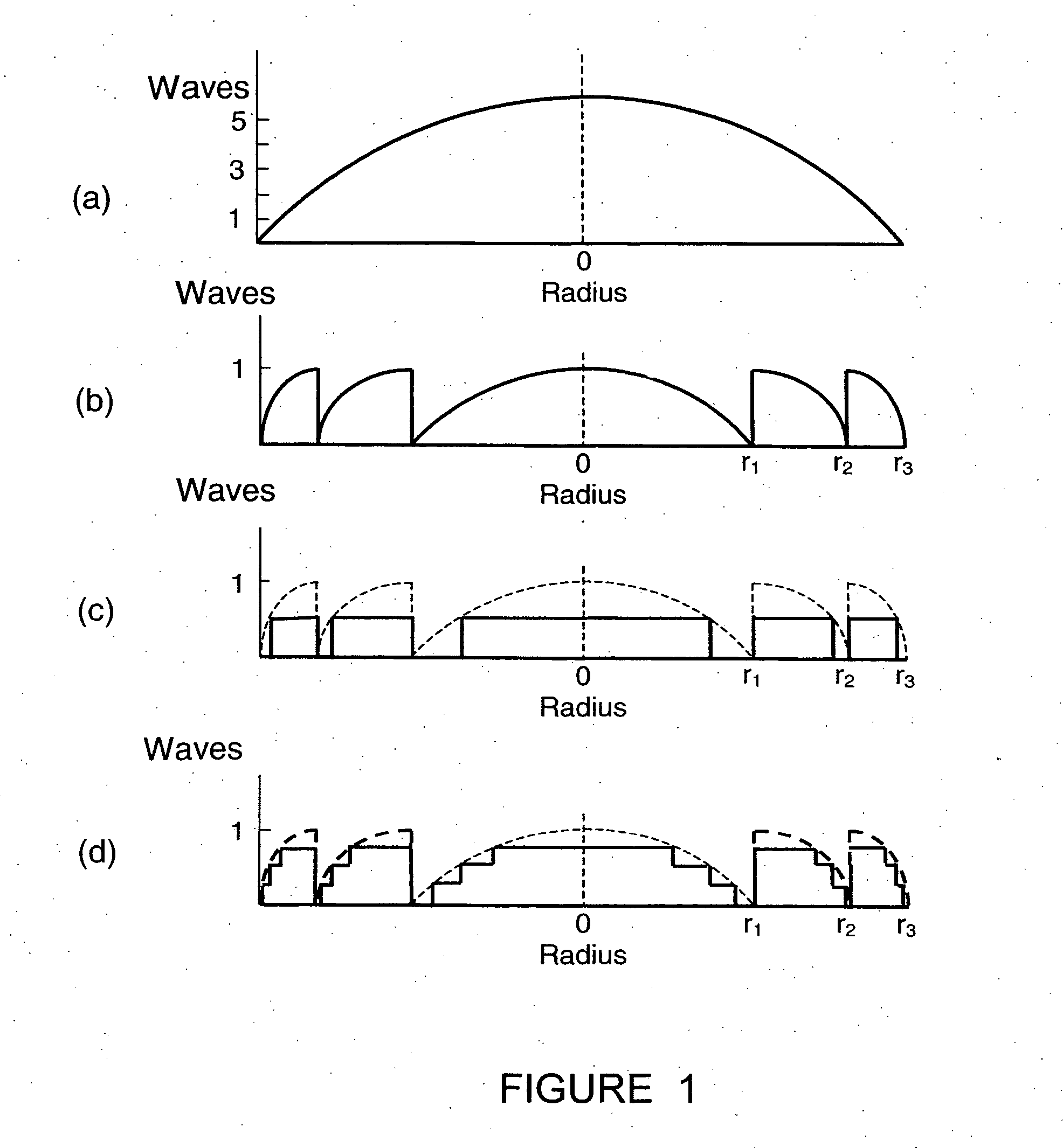
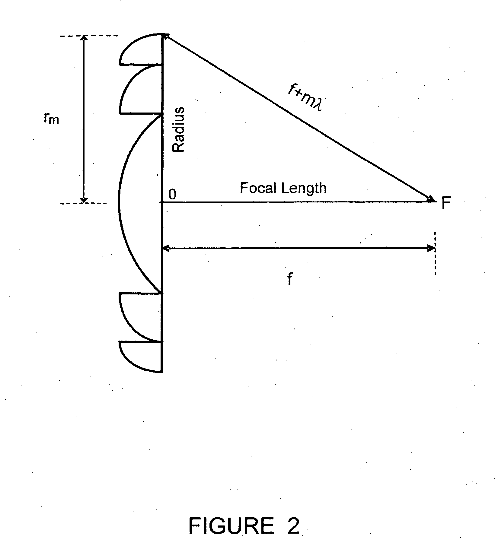
[0028] Diffractive lenses are known in the art. The function of a diffractive lens is based on near-field diffraction by a Fresnel zone pattern. Each point emerging from the structure serves as an emitter of a spherical wave. The optical field at a particular observing point is a summation of the contributions of the emitted spherical waves over the entire structure. Constructive interference of the spherical waves coming from the various points creates a high intensity at the observation point, corresponding to a high diffraction efficiency.

[0029]FIG. 1 shows an illustration of a diffractive lens: graph (a) is a conventional refractive lens; graph (b) is a diffractive lens with continuous quadratic blaze profile; graph (c) is a binary diffractive lens; and...


PUM


Abstract

An adjustable focusing electrically controllable electroactive lens is provided. The adjustable focusing electrically controllable electroactive lens can adjust the focal length discretely or continuously. The lens can be incorporated in a variety of optical devices including spectacles.

Description

CROSS-REFERENCE TO RELATED APPLICATIONS [0001] This application claims priority to U.S. Provisional Application No. 60 / 645,839 filed Jan. 21, 2005, which is incorporated herein by reference in its entirety.BACKGROUND OF THE INVENTION [0002] Correction of age-related optical changes in the eye becomes increasingly important as the life expectancy continues to increase. One age-related optical change in the eye is presbyopia, where people have difficulty in focusing close objects onto the retina because of decreased lens flexibility. Presbyopia usually begins to affect people in their forties, so there is a significant need for this vision correction. Ophthalmic lenses with fixed focusing properties have been widely used as spectacles and contact lenses to correct presbyopia and other conditions. [0003] Ophthalmic lenses are most useful if they have adjustable focusing power (i.e., the focusing power is not static). Adjustable focusing power provides the eye with an external accommoda...

Claims


Application Information

Patent Timeline
IPC IPC(8): G02F1/13
CPCG02F1/29G02F1/13G02F1/294G02B3/14G02C7/083
Inventor PEYGHAMBARIAN, NASSERLI, GUOQIANGAYRAS, PEKKA
Owner JOHNSON & JOHNSON VISION CARE INC
Learn More