
Controlling ink migration during the formation of printable electronic features

a technology of electronic features and ink migration, which is applied in the direction of conductive pattern formation, dielectric characteristics, coatings, etc., can solve the problems of affecting the final product properties, affecting the flow of electrons, and affecting the properties of electronic ink prior to printing,

Inactive Publication Date: 2006-07-20
CABOT CORP
View PDF100 Cites 190 Cited by
  • Summary
  • Abstract
  • Description
  • Claims
  • Application Information

AI Technical Summary

Benefits of technology

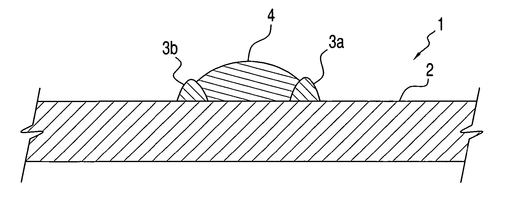
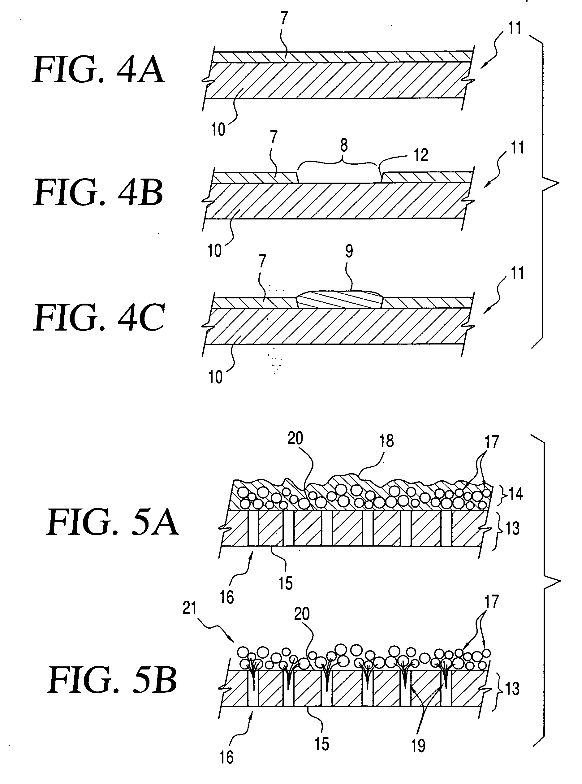
[0007] The present invention is directed to processes for limiting longitudinal and/or lateral ink migration during the formation of printable electronic features. In one embodiment, the invention is to a process for forming at least a portion of an electronic feature, the process comprising the steps of: (a) providing a first substrate having a first surface; (b) modifying the

Problems solved by technology

That is, the electronic ink, prior to printing, may or may not allow for the flow of electrons, e.g., be conductive.
Impurities are those materials that are not intended in the final product (e.g., the electronic feature) and that adversely affect the properties of the final product.
Loadings in excess of the preferred amounts can lead to undesirably high viscosities and / or undesirable flow characteristics.
On the contrary, the vehicle will usually not remove the anti-agglomeration substance from the surface of the nanoparticles to more than a minor extent, if at all.

Method used


Image

  • Controlling ink migration during the formation of printable electronic features
  • Controlling ink migration during the formation of printable electronic features
  • Controlling ink migration during the formation of printable electronic features

Examples


example 1

A. Example 1

Treating a Kapton Substrate with a Hydrophobic Chemical Agent

[0244] The following are examples that demonstrate the effect of treating a Polyimide (Kapton) film with a hydrophobic chemical agent combined with printing a silver nanoparticle-containing ink onto the substrate.

[0245] An ITI XY print system equipped with a Spectra SX-128 ink jet head was set up to print a silver nanoparticle-containing ink comprising approximately 55 weight percent silver. An image comprising single pixel lines having a resolution of 1,050 dots per inch was created and used in this example. The Kapton substrate was cleaned by wiping the substrate with denatured ethanol to remove some of the organic contaminants.

[0246] Sample 1 (control) did not receive any additional surface modification and was not treated with a hydrophobic chemical agent. Once the ink was deposited onto the substrate via the Spectra SX-128 ink jet head, the substrate was placed in a forced air convection oven at 200° C....

example 2

B. Example 2

Treating a LCD Glass Substrate with a Hydrophobic Chemical Agent

[0249] A second example demonstrated the effect of treating a Liquid Crystal Display (LCD) Glass substrate, or more specifically, Eagle 2000 by Corning Inc., with a hydrophobic chemical agent combined with printing a silver nanoparticle-containing ink onto the substrate.

[0250] An ITI XY print system equipped with a Spectra SX-128 ink jet head was set up to print a silver nanoparticle-containing ink comprising approximately 55 weight percent silver. Images comprising single pixel lines and having a resolution of both 750 dots per inch (Sample 3) and 1,050 dots per inch (Sample 4) were created and used in this example. The LCD Glass substrate was cleaned by wiping the substrate with denatured ethanol to remove some of the organic contaminants.

[0251] Sample 3 (control) did not receive any additional surface modification and was not treated with a hydrophobic chemical agent. Further, the 750 dots per inch ima...


PUM

PropertyMeasurementUnit
Surface energyaaaaaaaaaa
Temperatureaaaaaaaaaa

Abstract

Processes for controlling ink migration during the formation of printable electronic features. In a preferred aspect, the invention is to a process for forming at least a portion of an electronic feature. The process includes the steps of: (a) providing a first substrate having a first surface; (b) modifying the first surface to form a modified surface; and (c) applying an ink to at least a portion of the modified surface, wherein the modified surface interacts with the ink to inhibit lateral and / or longitudinal migration of the applied ink, and wherein the applied ink forms at least a portion of the electronic feature. In another aspect, the invention is to a process for encouraging electronic ink spreading with a surfactant.

Description

CROSS REFERENCE TO RELATED APPLICATIONS [0001] This application claims priority to U.S. Provisional Patent Application Ser. Nos. 60 / 643,577; 60 / 643,629; and 60 / 643,378; all filed on Jan. 14, 2005, and to U.S. Provisional Patent Application Ser. No. 60 / 695,403, filed on Jul. 1, 2005, the entireties of which are incorporated herein by reference.FIELD OF THE INVENTION [0002] The present invention relates to controlling ink migration during the formation of printable electronic features. More particularly, the invention relates to controlling migration of an ink on a substrate during the formation of the printable electronic features. BACKGROUND OF THE INVENTION [0003] The electronics, display and energy industries rely on the formation of coatings and patterns of conductive materials to form circuits on organic and inorganic substrates. The primary methods for generating these patterns are screen printing for features larger than about 100 μm and thin film and etching methods for featu...

Claims


Application Information

Patent Timeline
IPC IPC(8): B05D5/12B05D3/00B05D1/36
CPCB82Y30/00H01L51/0005H01L51/0022H05K1/16H05K3/12H05K3/1208H05K3/125H05K3/1258H05K3/245H05K3/386H05K2201/0116H05K2201/09909H05K2203/013H05K2203/0568H05K2203/1173H10K71/135H10K71/611
Inventor KOWALSKI, MARK H.HAUBRICH, SCOTT THOMASJAMES, ANTHONY R.
Owner CABOT CORP
Learn More