
Reconfigurable fixture device and methods of use

a fixture and reconfiguration technology, applied in the direction of manufacturing tools, metal-working machine components, shaping tools, etc., can solve the problems of long time required for reconfiguration, inability of modular fixtures and inability to adapt to different sizes and shapes of parts within a part family

Active Publication Date: 2006-07-20
GM GLOBAL TECH OPERATIONS LLC
View PDF1 Cites 50 Cited by
  • Summary
  • Abstract
  • Description
  • Claims
  • Application Information

AI Technical Summary

Benefits of technology

[0014] In yet another embodiment, a computer program product for fixturing a workpiece includes a storage medium readable by a processing circuit and storing instructions for execution by the processing circuit for facilitating a method comprising detecting a parameter associated with a reconfigurable fixturing device with at least one sensor to produce at least one parameter defining signal; processing the at least one

Problems solved by technology

However, modular fixtures have no intrinsic ability to adapt to different sizes and shapes of parts within a part family.
In addition, the time necessary for reconfiguration is long.
While an excellent means of facilitating the holding of complex parts, encapsulation is a costly and time-consuming process.
To date, however no feasibility studies have been conducted regarding the applicability of any of these techniques to production machining operations.
One troublesome area in flexible manufacturing systems is its implementation in body shops.
Clamps are typically employed to clamp the various sheet metal workpieces (e.g., body panels) during assembly and clamping can potentially scratch the exposed surface and / or locally deform the workpiece or surface coating, affecting its aesthetic quality.
While, ideally, clamping could be performed on flanges or surfaces that are invisible or immaterial to end users, some clamping inevitably occurs on surfaces whose quality is important aesthetically.
A problem arises if multiple models having significantly different workpiece configurations are to be produced on the same tooling setup.
A problem arises if multiple models are produced having significantly different workpiece configurations.

Method used


Image

  • Reconfigurable fixture device and methods of use
  • Reconfigurable fixture device and methods of use
  • Reconfigurable fixture device and methods of use

Examples


Embodiment Construction

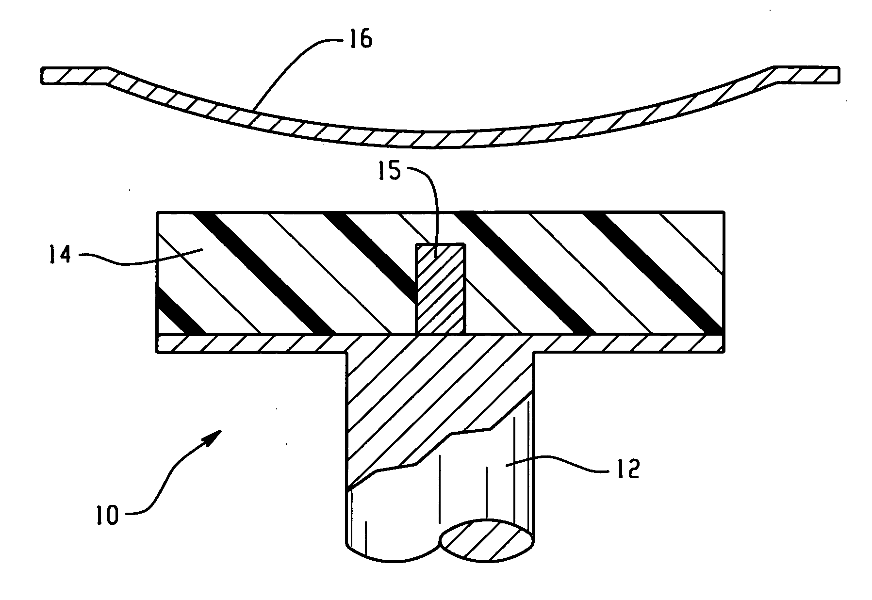
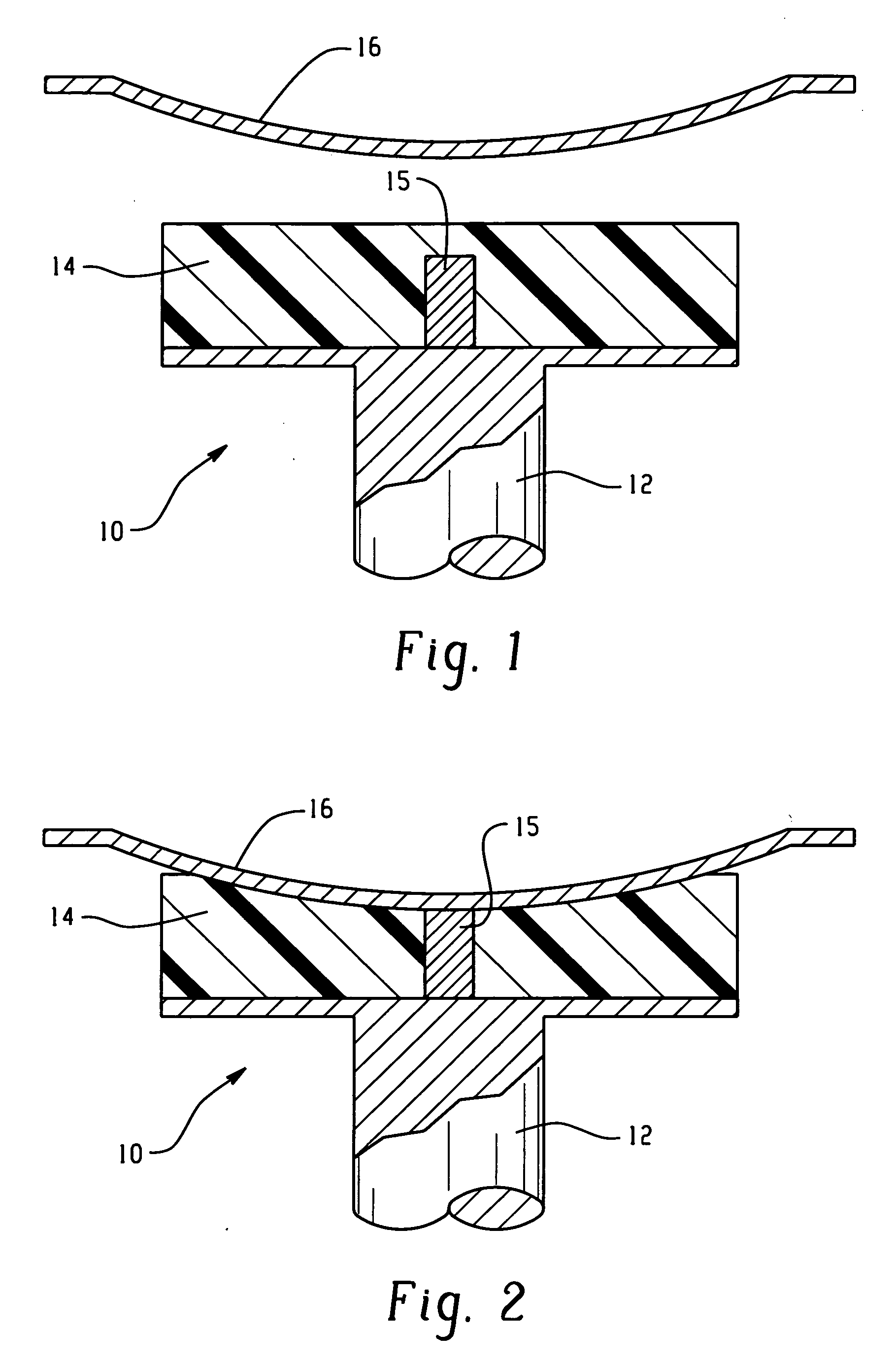
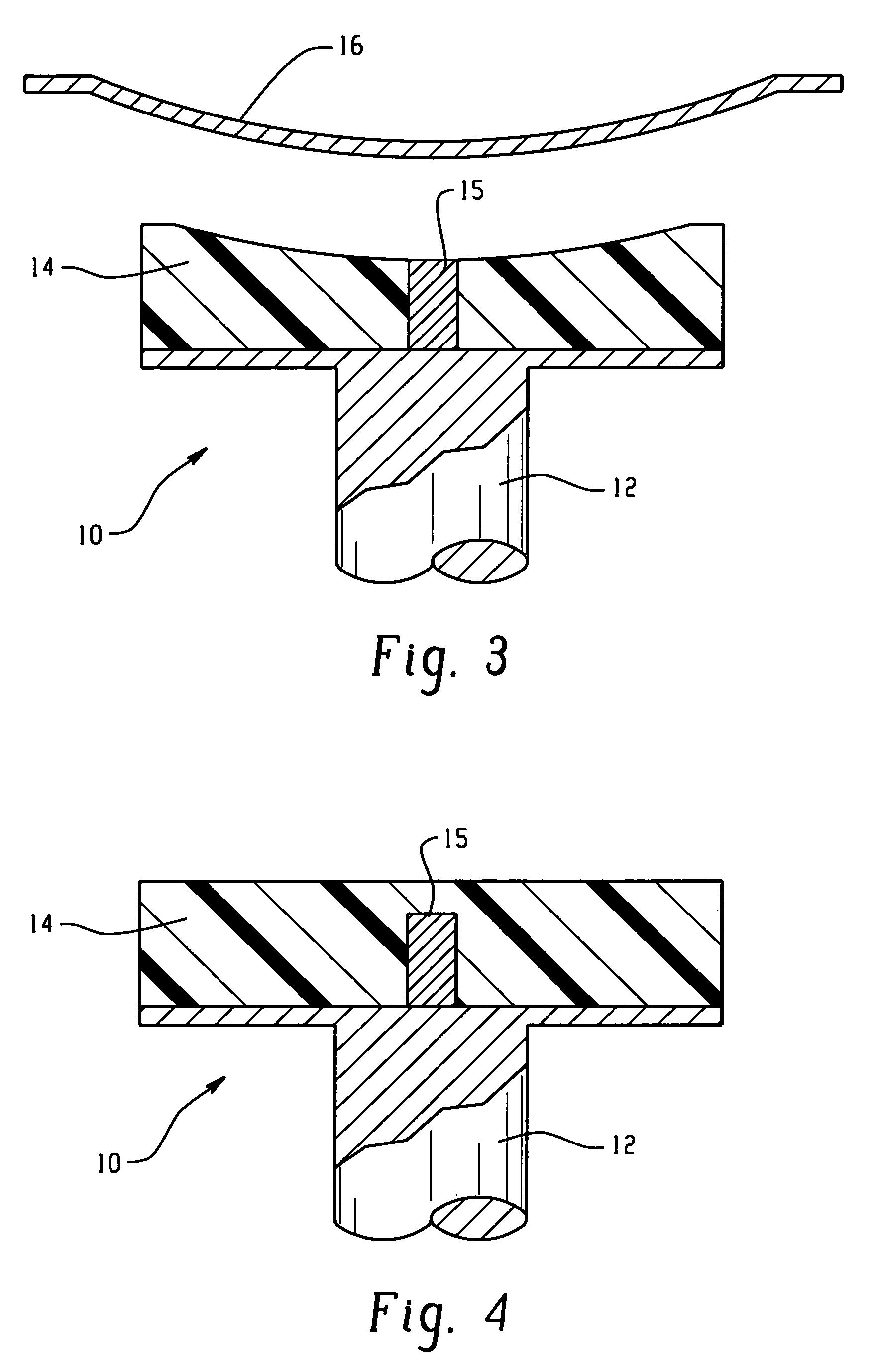
[0027] Disclosed herein are reconfigurable fixture devices for providing support and / or securement of a variety of dissimilar workpieces such as may be desired for a flexible manufacturing system. Suitable workpieces for loading onto the fixture device are those that are sufficiently rigid so as not to flex or distort under the weight of the workpiece or by any clamping force (which can be as high as 500 pounds distributed over roughly 1 square inch) when using the fixture device. Although reference will be made to its use in fixturing body panels for motor vehicles (e.g., cars, trucks, motorcycles, boats, airplanes, and the like), it should be understood that the reconfigurable fixture devices could be employed for a variety of end use applications where it may be desirable to support and / or clamp dissimilar workpieces using the same tooling setup without requiring manual adjustment or reprogramming. For example, the reconfigurable fixture devices can be employed for fixturing thin...


PUM

PropertyMeasurementUnit
Temperatureaaaaaaaaaa
Shape memory effectaaaaaaaaaa
Surfaceaaaaaaaaaa

Abstract

A reconfigurable fixture device system, including: a base member; a reconfigurable pad disposed on the base member, wherein the reconfigurable pad comprises a shape memory material configured to selectively conform to a surface contour of a workpiece; an activation device in operative communication with the shape memory material; a controller in operable communication with at least one of the reconfigurable pad, the activation device, and the base member; a plurality of sensors for sensing a parameter associated with at least one of the reconfigurable pad, the base member, the fixture device, and the workpiece, wherein the plurality of sensors is in operable communication with the controller; and an actuator in operable communication with the controller and the at least one of the reconfigurable pad, the base member, the fixture device, and the workpiece.

Description

CROSS REFERENCE TO RELATED APPLICATIONS [0001] The present application relates to, and claims the benefit of, U.S. Provisional Patent Application No. 60 / 645,263, which was filed on Jan. 19, 2005 and is incorporated herein in its entirety.BACKGROUND [0002] The present disclosure generally relates to a flexible manufacturing system and, more particularly, to a reconfigurable fixture device for clamping and / or providing support for a variety of different workpiece configurations. [0003] The advent of assembly lines has enabled rapid, mass production of products at a reduced product cost. Assembly lines typically include multiple operation stages and component, material, or sub-assembly inputs. Sometimes the workpieces are similar or related part shapes. Other times, the workpieces are of unrelated design but require similar manufacturing operations. In these varied applications, the fixture reconfiguration or changeover from one part design to another has to be fast enough to meet the ...

Claims


Application Information

Patent Timeline
IPC IPC(8): B21D37/02
CPCB23Q3/086B25B5/163Y10T29/49805Y10T29/53961Y10T29/4976Y10T29/49998Y10T29/53991
Inventor MANKAME, NILESH D.WELLS, JAMES W.HENRY, CHRISTOPHER P.SEARS, IVAN G.LINN, DOUGLAS M.BROWNE, ALAN L.SKURKIS, RICHARD J.
Owner GM GLOBAL TECH OPERATIONS LLC
Learn More