
High areal density holographic data storage system

a data storage system and high areal density technology, applied in the field of high areal density holographic data storage system, can solve the problems of limited improvement roadmaps for achieving increased data density, limited data rate achievable, random access, etc., and achieve the effect of high areal density of stored information

Inactive Publication Date: 2006-07-13
POSTECH CO LTD
View PDF14 Cites 25 Cited by
  • Summary
  • Abstract
  • Description
  • Claims
  • Application Information

AI Technical Summary

Benefits of technology

[0018] The invention further provides a method and apparatus for utilizing moderately high (>0.2) to high NA (≦0.85) components in HDS systems, so as to achieve high areal density of stored information (≧24 bits / μm2) when the recording geometry of the reference beam and object beam comprises a non 90 degree interbeam angle, such as would be the case for photopolymerizable, or photochromic, or organic photorefractive recording media.

Problems solved by technology

These technologies, for the most part, have relatively limited improvements remaining on their roadmaps for attaining increased data density, or have limitations in achievable data rates, or in random access.
Unfortunately, the use of high NA (NA ≧0.2 for HDS systems) lenses, such as in the conventional 4f optical system wherein the first and second Fourier transform lens are a matched pair and thus have identical values of NA, can introduce several factors that contribute to the substantial decreases of signal-to-noise (SNR) in the HDS system.
A typical HDS system has several potential sources of optical noise including the aforementioned light scattered from the media and / or optical components, reflections from surfaces internal to the drive, and, additionally, image misalignment and distortion.
In general, each of these potential noise sources become increasingly more evident and problematic in systems that endeavor to maximize areal density of stored data.

Method used


Image

  • High areal density holographic data storage system
  • High areal density holographic data storage system
  • High areal density holographic data storage system

Examples


Embodiment Construction

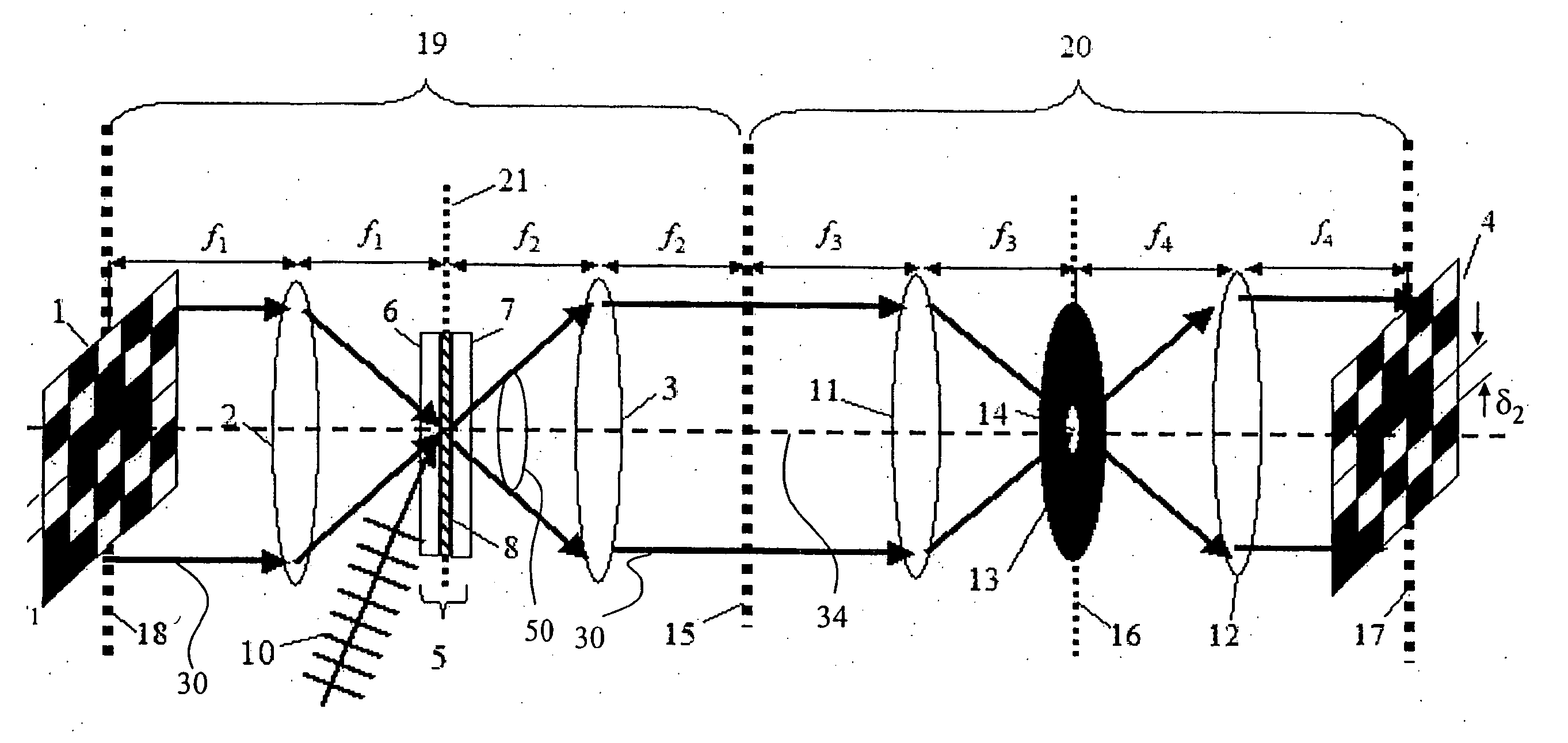
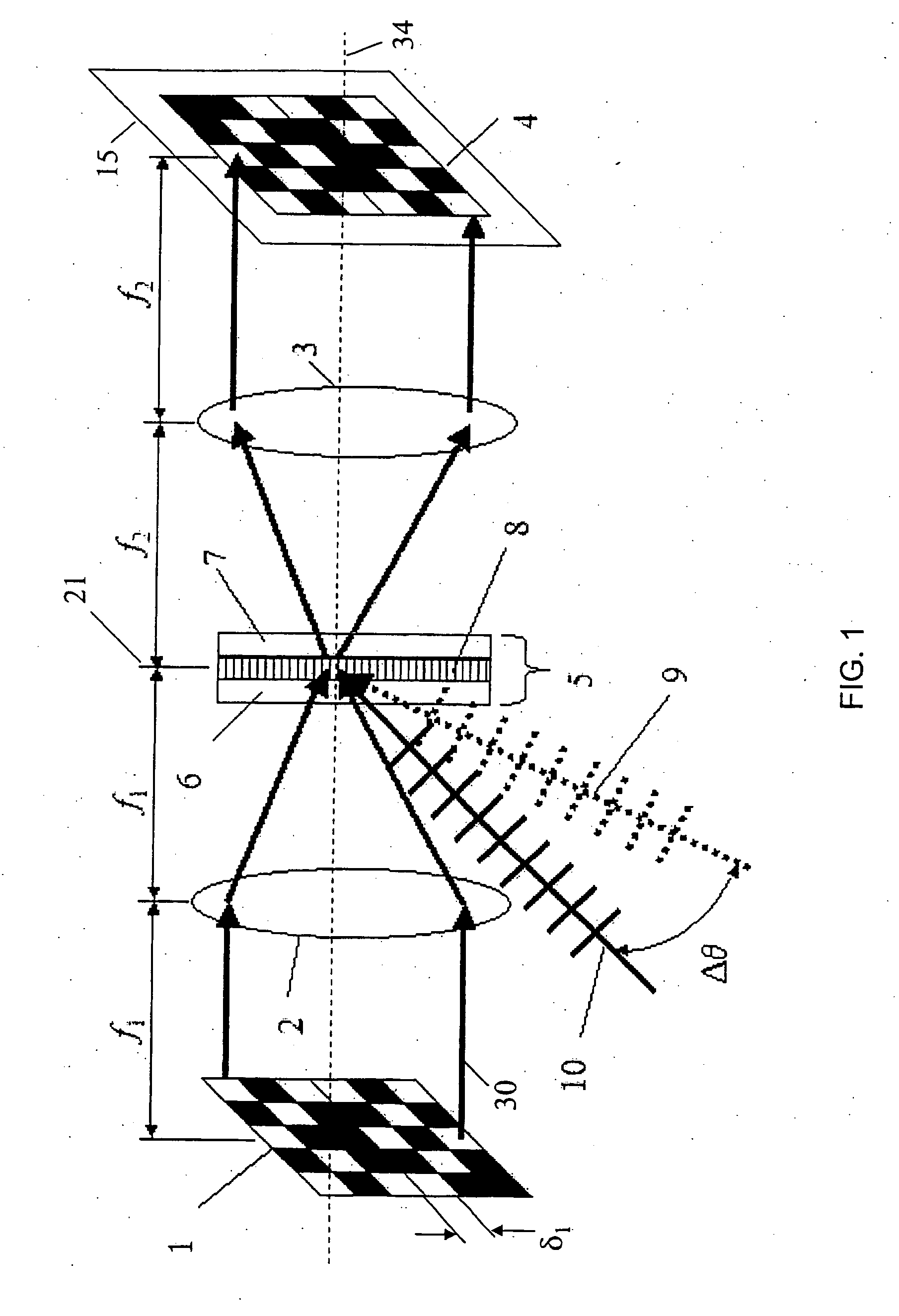
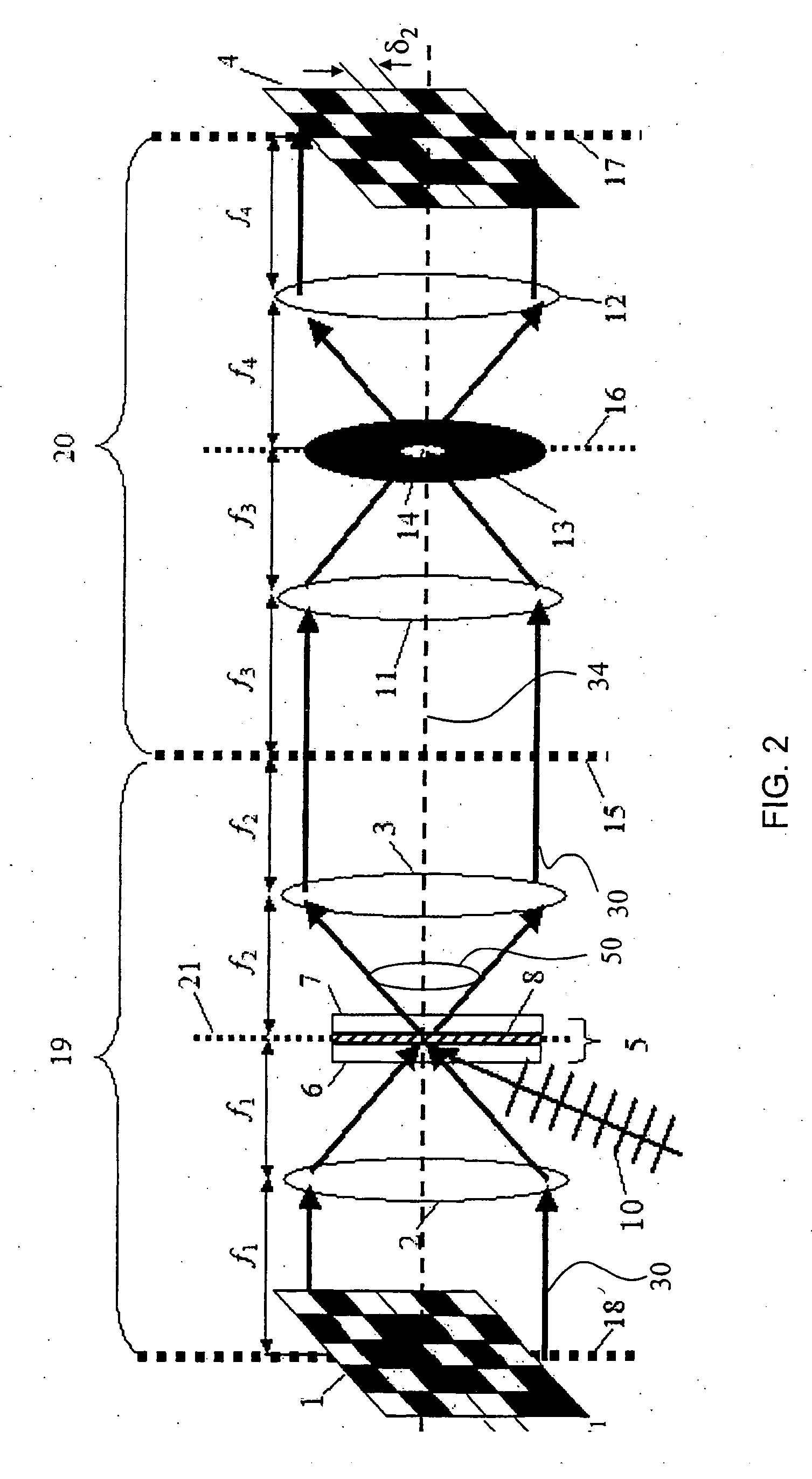
[0027] The elements of a 4f optical design are presented in FIG. 1. Signal beam 30 passes through a two dimensional array of substantially transparent or opaque pixels that are formed by the spatial light modulator (SLM) 1. Alternatively, a one dimensional array of substantially transparent or opaque pixels may be used, or the signal beam may instead reflect from a two dimensional or one dimensional array of pixels that are formed by the SLM. SLM 1 encodes signal beam 30 with data information that is to be recorded. The SLM typically modulates either the amplitude or the phase of an incident light beam, and can operate by transmission, as shown in FIG. 1, or by reflection of the incident beam to encode the data information in signal beam 30. A 4f optical arrangement of FIG. 1 comprises Fourier transform lens element (a first imaging lens element) 2, having focal distance f1, that operates to relay a Fourier transform of SLM-encoded signal beam 30 to plane 21 that is one focal distan...


PUM

PropertyMeasurementUnit
thicknessaaaaaaaaaa
thicknessaaaaaaaaaa
thicknessaaaaaaaaaa

Abstract

An apparatus for recording or reading high areal density holographically stored information with high signal-to-noise ratio. The apparatus comprises a holographic imaging system for recording or reconstructing a holographic image, having a first numerical aperture and a first focal length and an additional optical system for filtering the signal beam, having a second numerical aperture and a second focal length, wherein the numerical aperture of the additional optical system is less than the numerical aperture of the holographic imaging system and / or the focal length of the additional optical system is greater than the optical length of the holographic imaging system.

Description

RELATED APPLICATIONS [0001] This application is a continuation of International Application No. PCT / US2004 / 018116, which designated the United States and was filed on Jun. 7, 2004, published in English, which claims the benefit of U.S. Provisional Application No. 60 / 476,812, filed on Jun. 7, 2003. The entire teachings of the above applications are incorporated herein by reference.BACKGROUND OF THE INVENTION [0002] The need for cost-effective, high performance data storage has, for many applications, outpaced technology development. Enterprise storage, image archives, and entertainment content, among other applications, are driving the demand for enhanced data storage solutions. Several of these applications currently rely on storage technologies, such as optical, magneto-optical, and magnetic tape, that use removable media. These technologies, for the most part, have relatively limited improvements remaining on their roadmaps for attaining increased data density, or have limitations...

Claims


Application Information

Patent Timeline
Patent Type & Authority Applications(United States)
IPC IPC(8): G03H1/28G11B7/0065G11B7/135G11C13/04
CPCG11B7/0065G11B7/1372G11B7/1381G11C13/042G11C13/00
Inventor BUTLER, CHRISTOPHER J.WALDMAN, DAVID A.
Owner POSTECH CO LTD
Learn More