
Vibration analysis

a vibration analysis and vibration technology, applied in the field of vibration analysis, can solve the problems of costly machine downtime, costly servicing, and difficult detection of faults within machines before mechanical damage occurs

Active Publication Date: 2006-07-13
MANTHEY DIANE MANT
View PDF3 Cites 188 Cited by
  • Summary
  • Abstract
  • Description
  • Claims
  • Application Information

AI Technical Summary

Benefits of technology

[0031] Preferably, the decimation or sub-sampling filter reduces the frequency of the envelope signal to at least approximate the lower cut-off frequency.

Problems solved by technology

Prior to the emergence of this analysis, faults within machines were difficult to detect before mechanical damage occurred.
Such faults often led to costly machine downtimes and costly servicing due to extensive mechanical damage.
However, by detecting and analysing vibrations produced by a machine, certain symptoms of impending fault or failure can be detected before major mechanical damage occurs.
When this is done on an industrial scale for a large number of machines, the data collection step can become costly simply due to the time involved in the collection.
When combined with the time required to walk between all of the measurement locations, to attach the sensor and to wait for it to settle, the collection process can become very time-consuming.
The main disadvantage of this system is that the resolution and extent of valuable data collected is reduced as a consequence of saving time and space.
However, since ‘saving all of the time data .
. . is simply too burdensome to be considered a realistic option’, Piety employs reduced-volume data collection by monitoring key parameters of the time data.
It is noted however that the independence of the parallel processing chains comes at a cost—the necessity for each chain to have a complete processing ability results in an increased cost of the device.

Method used


Image

  • Vibration analysis
  • Vibration analysis
  • Vibration analysis

Examples


Embodiment Construction

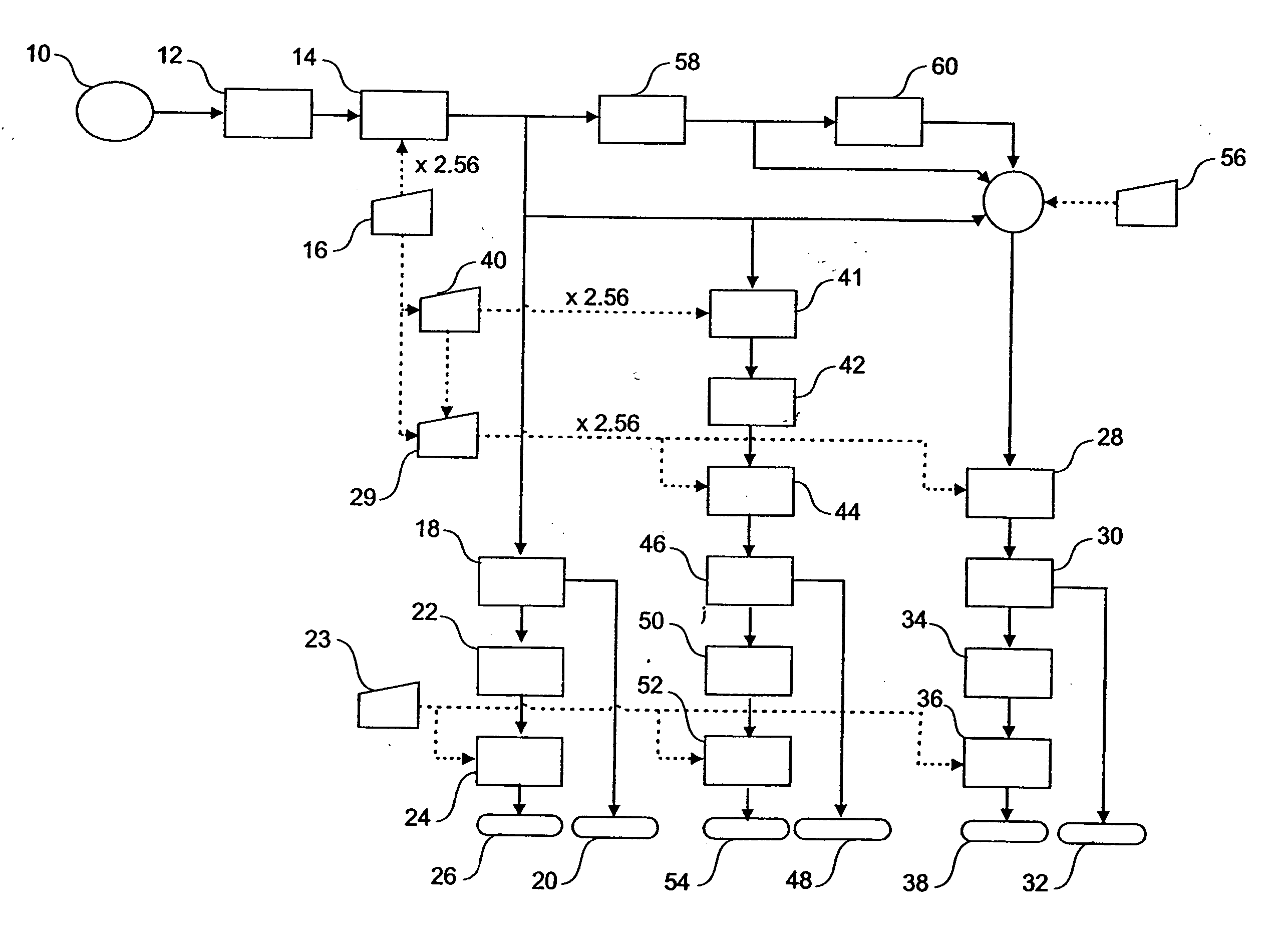
[0039] As used herein, the term ‘type’ in reference to signals refers to the composition of frequencies in the signal. This includes, without limitation, high frequency signals comprising substantially only frequencies less than an upper cut-off frequency, low frequency signals comprising substantially only frequencies less than a lower cut-off frequency and demodulation signals comprising frequencies that have been demodulated in the manner hereinafter described.

[0040] As used herein, the term ‘electrical vibration signal’ refers to a vibration signal expressed in electrical form. Such an electrical form is commonly obtained using a vibration sensor (such as an accelerometer) to convert the mechanical vibrations of an object into electrical signals that represent the mechanical vibrations. Electrical vibration signals may be saved in some form of electronic storage means, such as memory banks or disk storage devices. The saved electrical vibration signals may later be retrieved an...


PUM

PropertyMeasurementUnit
frequenciesaaaaaaaaaa
frequencyaaaaaaaaaa
cut-off frequencyaaaaaaaaaa

Abstract

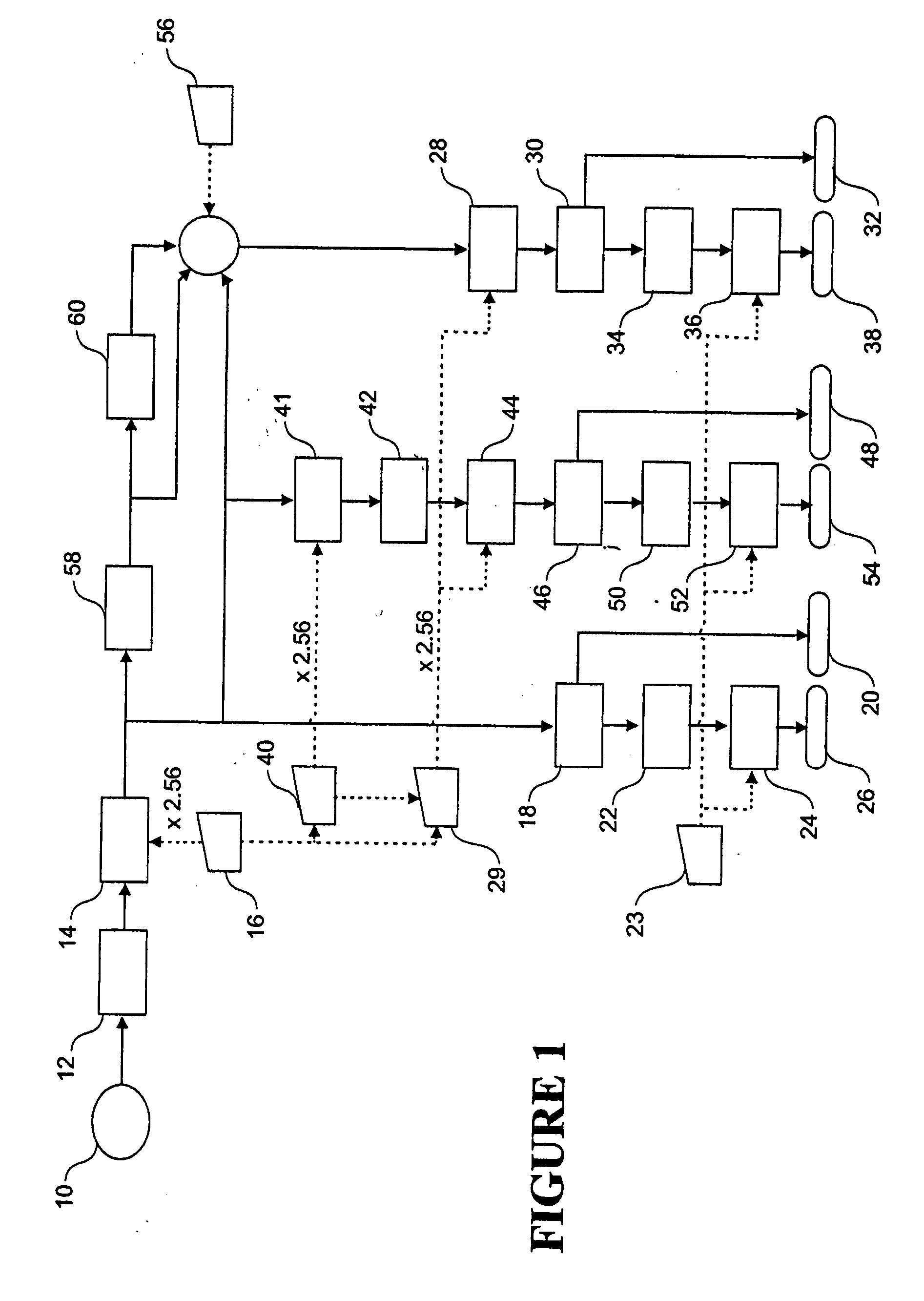
The present invention relates to vibration analysis and in particular, but not limited to, the derivation of multiple types of vibration signals from one vibration signal for vibration analysis. In the preferred method of the invention the vibrations of an object are measured using at least one vibration sensor, wherein the vibration sensor converts vibrations into an electrical vibration signal. The electrical vibration signal is digitised based on a first frequency, wherein the first frequency is selected from a plurality of possible frequency values. A first type of vibration signal is derived from the digitised vibration signal. A second type of vibration signal is then derived from the digitised vibration signal based on a second frequency. The second frequency is rationally determined from, and lower than, the value selected for the first frequency. The invention also provides apparatus for deriving multiple types of vibration signals from one measured vibration signal for vibration analysis.

Description

CROSS-REFERENCE TO RELATED APPLICATIONS [0001] This application claims the benefit of priority of the New Zealand Patent Application Serial No. 537244 entitled “Improvements in or Relating to Vibration Analysis”, filed Dec. 16, 2004. Benefit of priority of the filing date of Dec. 16, 2004 is hereby claimed, and the disclosure of the said Patent Application is hereby incorporated by reference. FIELD OF THE INVENTION [0002] The present invention relates to vibration analysis and in particular, but not limited to, the derivation of multiple types of vibration signals from one vibration signal for vibration analysis. BACKGROUND TO THE INVENTION [0003] Vibration analysis is commonly used in the art of fault-detection in machines. Prior to the emergence of this analysis, faults within machines were difficult to detect before mechanical damage occurred. Such faults often led to costly machine downtimes and costly servicing due to extensive mechanical damage. However, by detecting and analy...

Claims


Application Information

Patent Timeline
Patent Type & Authority Applications(United States)
IPC IPC(8): G01N29/00
CPCG01H1/14G01M13/028G01N29/07G01N29/12G01N29/42G01N29/46
Inventor LEIGH, NIGEL
Owner MANTHEY DIANE MANT
Learn More