
Ophthalmologic apparatus and related positioning method

a positioning method and ophthalmologic technology, applied in the field of ophthalmologic devices and related positioning methods, can solve the problems of substantially complicated and difficult to supervise the overall devi

Active Publication Date: 2006-07-06
CARL ZEISS MEDITEC AG +1
View PDF18 Cites 9 Cited by
  • Summary
  • Abstract
  • Description
  • Claims
  • Application Information

AI Technical Summary

Benefits of technology

[0010] It is the primary object of the present invention to develop an ophthalmologic device and a method for control thereof in which sources of subjective errors are minimized in the alignment of the device to the optical axis of the eye so that the measurements to be determined are exact and reliable. The user is no longer required to make a rough adjustment. The device is not substantially more complicated with respect to its construction and applicability.
[0012] The ophthalmologic device for determining biometric data of an eye has many applications both in medicine and in optometry. A significant savings in time is achieved due to the automatic positioning. In some ophthalmologic devices, light marks and light patterns are already tracked by eye tracker units for eye movement, so that their use for eye detection does not represent an increased cost or further complication of technical apparatus.

Problems solved by technology

This solution is disadvantageous compared with the method suggested in the present application due to the fact that the measurement unit of the ophthalmologic device must be roughly oriented by the user by means of a joystick at the start of the examination, i.e., when the patient sits in front of the device and the patient's eye has been brought into a fixed position.
The known technical solutions have the disadvantage that exact alignment of the measurement device to the eye either depends subjectively upon the user in the absence of automatic positioning or that additional technical devices are always required when automatic positioning is provided, which makes the overall device substantially more complicated and harder to oversee.

Method used


Image

  • Ophthalmologic apparatus and related positioning method
  • Ophthalmologic apparatus and related positioning method
  • Ophthalmologic apparatus and related positioning method

Examples


Embodiment Construction

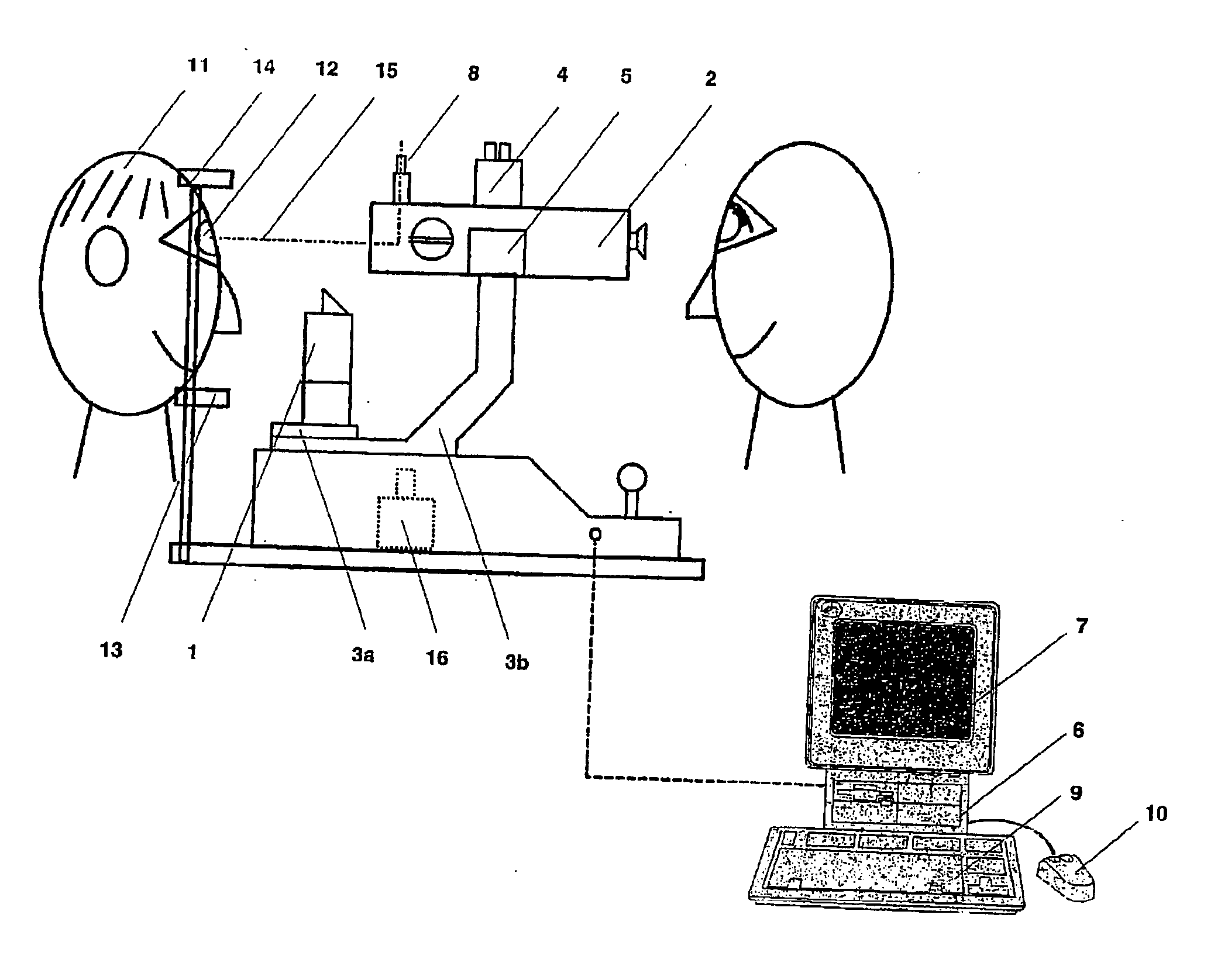
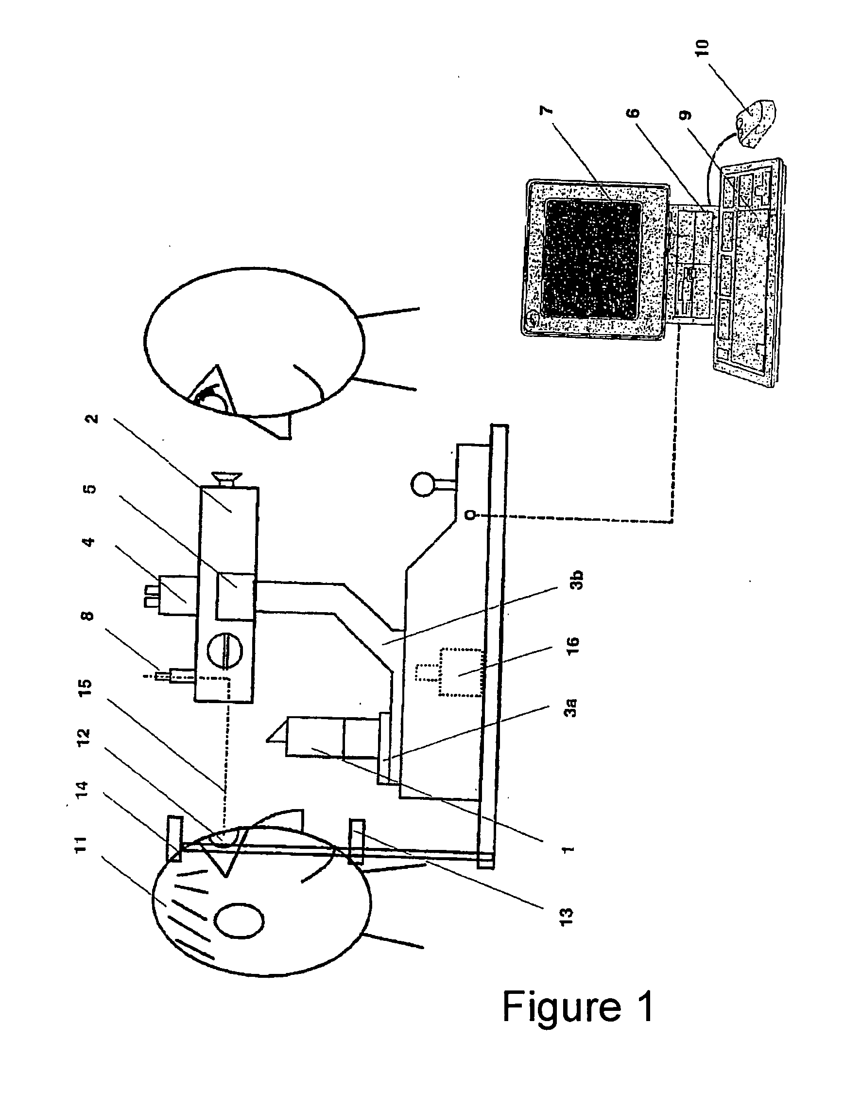
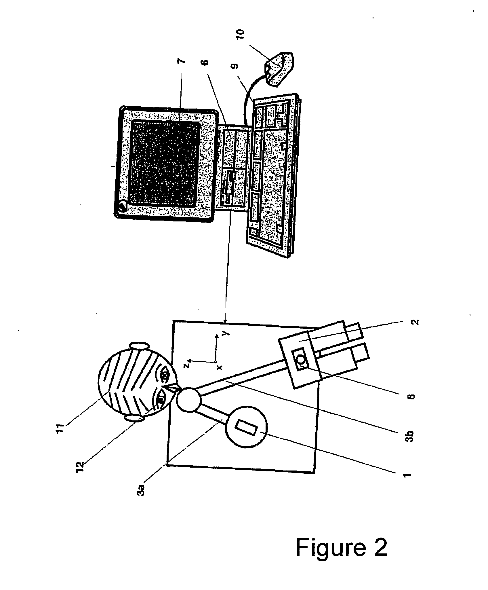
[0017] An ophthalmologic device, for example, for determining biometric data of an eye, is shown schematically in FIG. 1 and comprises a preferably digitally controllable illumination unit 1 and, as observation system, a stereo microscope 2 with different magnifications that are arranged on separate supporting arms 3a and 3b so as to be swivelable independent of one another. A special eye tracker unit 8 is connected to an associated IR illumination unit, which works in synchronization with the image rate of the eye tracker unit 8, and a central control unit 6 for detecting, processing and storing data. The IR illumination ensures that no influence can be exerted with the actual high-resolution digital recording camera in the VIS range. The camera beam path and eye tracker beam path are accordingly optically separated with respect to spectrum and cannot influence one another. A suitable IR bandpass filter that is transparent only for the light of the IR illumination unit is provided ...


PUM


Abstract

The present invention is directed to an arrangement and method for positioning the device with respect to the patient's eye to be examined in x-, y- and / or z-coordinates. The ophthalmologic device comprises a controllable illumination unit, an observation system, an image recording unit, a central control unit, an output unit, an eye tracker unit, and means for relative positioning. The imaging system of the eye tracker unit has at least two different adjustable magnifications. In the method for positioning the ophthalmologic device, the signal of the eye tracker unit is used not only to track a measuring mark and / or grid structure projected on the eye but also to detect the position of the patient's eye with respect to the optical axis of the ophthalmologic device. The solution proposed with the ophthalmologic device according to the invention makes it possible to automatically position the entire device with respect to the eye to be examined. The examination and determination of the biometric data of an eye can be simplified and substantially accelerated in this way.

Description

CROSS-REFERENCE TO RELATED APPLICATIONS [0001] This application claims priority of International Application No. PCT / EP2003 / 011925, filed Oct. 28, 2003 and German Application No. 102 50 569.1, filed October 28, the complete disclosures of which are hereby incorporated by reference.BACKGROUND OF THE INVENTION [0002] a) Field of the Invention [0003] The present invention is directed to an arrangement and method for automatic positioning of the device with respect to the patient's eye to be examined in the x, y and / or z coordinates. This method can advantageously be used to facilitate the determination of biometric data of the eye and other adjustments relating to diagnostics and therapy based on manual or stored method sequences. Data from an examination can be stored in order to examine the corresponding regions in another, subsequent examination under the same conditions so that changes can be determined. [0004] b) Description of the Related Art [0005] Technical solutions in which a...

Claims


Application Information

Patent Timeline
Patent Type & Authority Applications(United States)
IPC IPC(8): A61B3/14A61B3/113
CPCA61B3/113
Inventor BAUMANN, OLIVERCLAUS, MICHAELDOERING, AXELKOSCHMIEDER, INGOSCHULZE, THOMASSPRUCK, BERND
Owner CARL ZEISS MEDITEC AG
Learn More