System for monitoring standard parts

a technology for standard parts and monitoring systems, applied in the direction of shaping tools, programme control, instruments, etc., can solve the problems of stress and deflection of guide pillars, deviation from congruence, etc., and achieve high acceleration and speed, high stroke frequency of forming or pressing tools, and high accuracy

Active Publication Date: 2021-04-08
AGATHON MASCHFAB
View PDF8 Cites 0 Cited by
  • Summary
  • Abstract
  • Description
  • Claims
  • Application Information

AI Technical Summary

Benefits of technology

[0009]It is therefore an object of the present invention to provide a system for measuring tool misalignment in a press device during set-up and during operation. Hereinafter, the term press device is related to a press machine, a molding machine, or the like as well. In particular, the system is robust enough to withstand oil atmosphere and detergent, and can be used in operation with high acceleration and speeds and high stroke frequencies of the forming or pressing tool. It is another object of the present invention to provide a system, which is provided to determine not only deformation of the guide means with high accuracy but also to detect the direction of deformation.
[0015]The strain gauge can be designed as a printed, deposited, or laser-structured strain gauge. In one embodiment of a strain gauge sensor a 3D printing technology for conductive materials is used for printing the strain gauge sensor. By directly printing of sensor structures on the substrate material a high design freedom and flexibility are achieved.
[0019]Using strain gauge sensors as measurement means have some major benefits such that these sensors and their application are state-of-the-art and therefore can be established in an easy way, that no or only few size constraints have to be considered, their fabrication is inexpensive and offers a high flexibility in sensor designs and the possibility to print these sensing elements on almost any surface.
[0022]The advantage by using the difference between the so-called post-deformation frequency and the reference frequency is to minimize all sources of possible errors. It is known, that the oscillation frequency of an oscillation circuit is a frequency according to the impedance including the inductive component and the capacitive component between the electrodes in addition to the electrical resistance component between the electrodes. Since inductive component and resistive component are constant, the oscillation frequency is only influenced by a change in capacity of the circuit. The difference between the frequency after deformation and the reference frequency substantially corresponds to the difference between only the electrical capacity of the sensor unit before and after the deformation and is thus directly related to the distance between the plates of the capacitor sensor unit. The signal noise and external error sources can be minimized by using the difference as a measurement setup.
[0023]In another embodiment according to the invention, measuring means accommodated into the longitudinal bore of at least one guide pillar are configured as a fiber optic sensor. The fiber optic sensor is configured to measure strain along an optical fiber, which can be embedded into the longitudinal bore provided in at least one of the guide pillars. In general, optical sensor devices are based on detecting modifications or modulations in some characteristics of light. Transmitted or reflected light can be modulated by changes in its amplitude, phase, frequency and / or polarization state. Fiber optic sensors are immune to electromagnetic interferences, chemically inert, withstand high temperatures and are potentially small and lightweight as well as they show excellent transmission capabilities and can provide a plurality of measuring points along a single optical fiber, which can be multiplexed to offer distributed measuring with great spatial resolution.

Problems solved by technology

For example, the tools, in particular the parts of the tool are not mounted such to be congruent to each other, leading to stress and deflection of the guide pillars.
Furthermore, problems can occur during operation of the tool for example due to a backlash or due to thermic effects which can result in deviation from congruence, as well as due to uneven punching force along the length of the punching tool or due to tilting of one of the parts of the tool.
Since the die press or mold press can show a certain amount of clearance of the guidance due to age and therefore the tool halves are no longer congruent to each other bending of guide pillars can result during operation.

Method used


Image

  • System for monitoring standard parts
  • System for monitoring standard parts
  • System for monitoring standard parts

Examples


first embodiment

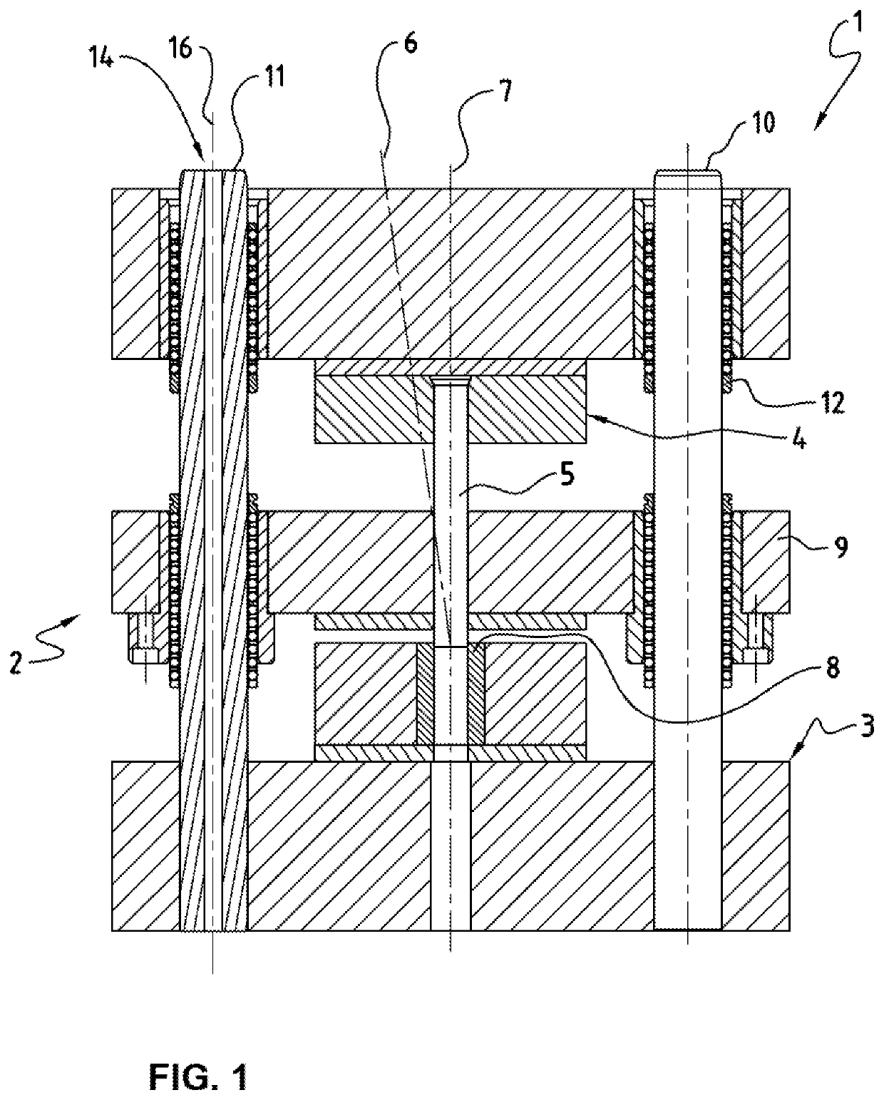
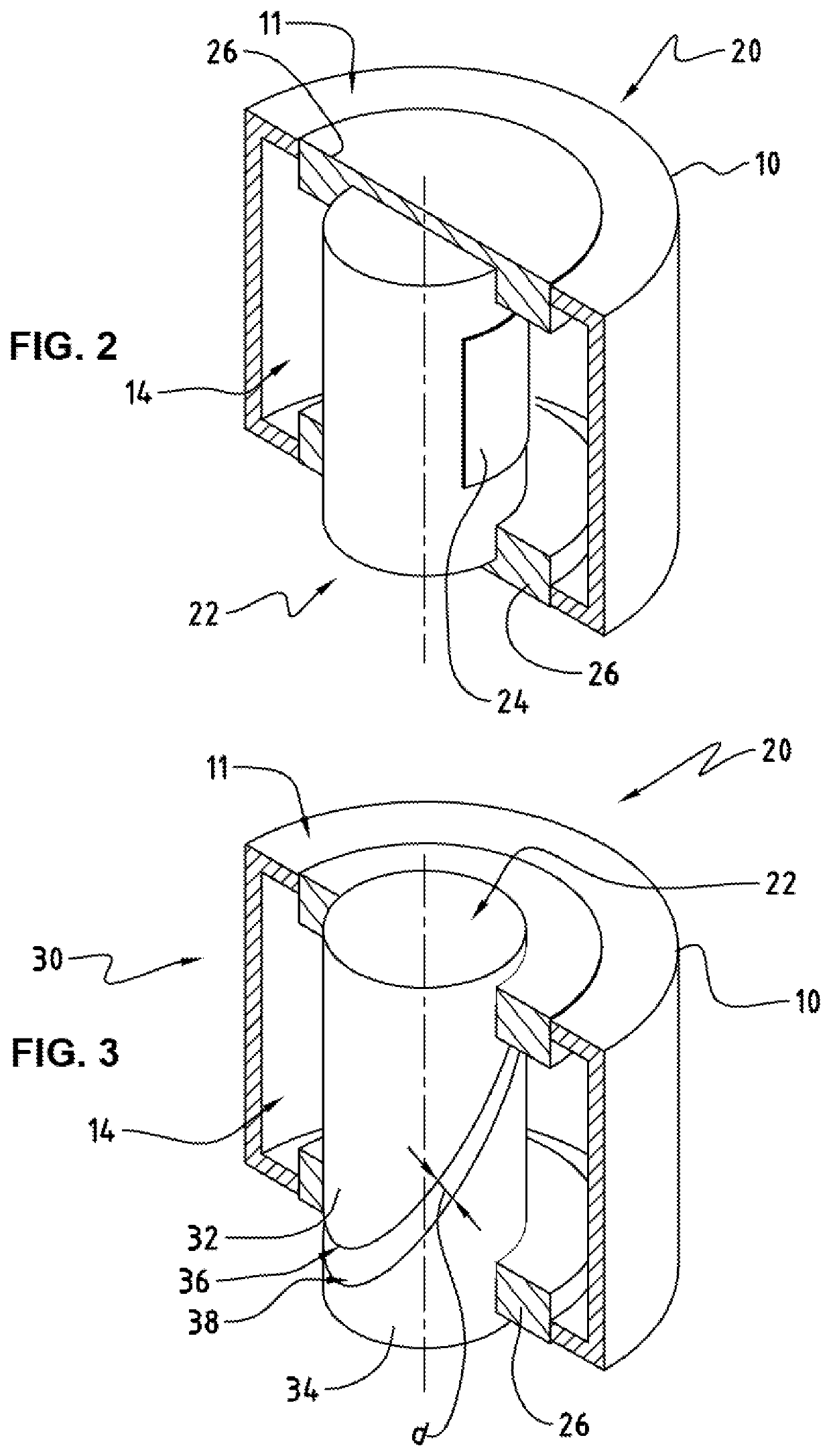
[0048]FIG. 2 shows a perspective view of a longitudinal section through a measurement means 20 according to the invention. The measuring means 20 comprises a pillar shaped structure 22 on which a surface sensing element in form of a strain gauge 24 is attached, forming a strain gauge sensor. The measuring means 20 is configured to be inserted into the longitudinal bore 14 of the guide pillar 10 and to be fixedly mounted to the end regions of the guide pillar 10 by holding elements. Therefore, at end regions of the pillar shaped structure 22 ring shaped elements 26 can be provided, which come to abut against the end faces 11 of the guide pillar 10 when the pillar shaped structure 22 is fully pushed into the longitudinal bore 14 and can be fixedly mounted in position e.g. by press fitting.

[0049]At a circumference of the pillar shaped structure 22 at least one strain gauge 24 is provided. Preferably, two strain gauges 24 are attached in pairs on opposite sides of the pillar shaped stru...

third embodiment

[0051]FIGS. 4a and 4b shows a measurement means 20 according to the invention. The FIGS. 4a and 4b show schematically a guide pillar 10 in which a fiber optic sensor 40 is embedded in the longitudinal bore 14 coaxially with the guide pillar axis 16. The optical sensor 40 is configured as a fiber optic sensor, in particular as an interferometric sensor comprising a process unit 42 comprising inter alia an interferometer such as a Fabry-Pérot-Interferometer, a transducer to convert an optical signal into an electrical signal and a processor. For example light from a low-coherence source (not shown) is divided into a measurement fiber 44 and a reference fiber 46 arranged inside of the measuring means 20. The measurement fiber 44 is connected to the measuring means 20 such that during bending the measurement fiber 44 is elongated. FIG. 4a shows the guide pillar 10 in a straight position. FIG. 4b shows the guide pillar 10 subjected to deflection that can be detected by the fiber optic se...


PUM

PropertyMeasurementUnit
diameteraaaaaaaaaa
distanceaaaaaaaaaa
temperatureaaaaaaaaaa

Abstract

System for measuring misalignment of a tool (2) in a press device (1), the tool (2) comprises at least a first part (3) and a second part (4), which are movable relative to another in a guided manner by means of guide means comprising at least a guide pillar (10) provided in the first part (3) which is led in a guide bush (12) provided in the second part (4), wherein the system comprises measuring means (20) provided to detect misalignment of the tool (2). According to the invention, the measuring means (20) are mounted directly at the guide means.

Description

TECHNICAL FIELD[0001]The invention relates to a system for monitoring standard parts, in particular for measuring misalignment of a tool in a press device used for stamping and / or molding, wherein deformation, deflection and / or strain of guiding means are measured.BACKGROUND OF THE INVENTION[0002]Press tools are used in hydraulic, pneumatic and / or mechanical presses to produce components, in particular sheet metal components in large numbers by blanking, piercing, bending, forming, punching etc. Machining devices for stamping, pressing or molding comprise either a stamping tool, a pressing tool, an injection-molding tool or a die-casting tool. In general, the tool comprises a plurality of plates, known as well as tool halves, movable relative to another and made up of at least a first part and a second part, in particular a punching or blanking die or a mold. The movement of the first part and the second part during a working stroke is guided by guiding means from a closed position,...

Claims


Application Information

Patent Timeline
Patent Type & Authority Applications(United States)
IPC IPC(8): B23Q17/22B23Q17/00B23Q17/24
CPCB23Q17/2216B23Q17/2476B23Q17/2457B23Q17/005G01B7/18G01B7/20G01B7/22G01B11/161B21C51/00B29C45/7653G05B2219/45131B30B15/0094B21D37/12B30B15/041
Inventor SCHOLZE, STEPHANSEATOVIC, DEJANALLENSPACH, MARKUSNOBS, STEFAN
Owner AGATHON MASCHFAB
Why Eureka
Try Eureka