
Over-sampling A/D converting circuit

a converting circuit and converting circuit technology, applied in the field of oversampling a/d converting circuits, can solve the problems of weak video noise coming to the surface, weak video noise may annoy viewers on the large screen of monitor devices, etc., and achieve the effect of accurate elimination of signal components, reduced aliasing noise, and improved s/n ratio

Inactive Publication Date: 2006-07-06
RENESAS ELECTRONICS CORP
View PDF4 Cites 6 Cited by
  • Summary
  • Abstract
  • Description
  • Claims
  • Application Information

AI Technical Summary

Benefits of technology

[0017] An aspect of the present invention relates to an over-sampling A / D converting circuit includes: an input receiving an analog video signal; and a filter unit limiting a frequency band of the analog video signal in accordance with a sampling frequency that varies depending on a color television system of the analog video signal. According to the circuit, it is possible to accurately eliminate a signal component not lower than the Nyquist frequency in accordance with a color television system, enabling a reduction in aliasing noise, a higher S / N ratio, and a high image quality obtained at a subsequent stage.
[0018] According to another aspect of the invention, an over-sampling A / D converting circuit includes: a first sampling unit executing A / D conversion on an input analog video signal with a first sampling frequency; a frequency band limiting filter unit allowing passage of a signal component in a predetermined passing band out of a signal passing through the first sampling unit; a second sampling unit sampling the passed signal with a second sampling frequency; and a switching unit switching the passing band of the frequency band limiting filter unit. According to the circuit, it is possible to accurately eliminate a signal component not lower than the Nyquist frequency in accordance with a color television system, enabling a reduction in aliasing noise, a higher S / N ratio, and a high image quality obtained at a subsequent stage.
[0019] According to the present invention, it is possible to provide an over-sampling A / D converting circuit capable of improving an S / N ratio regardless of the color television system.

Problems solved by technology

In such television receivers, a problem about a displayed image such as weak video noise comes to the surface albeit being ignorable on a small screen.
However, a weak video noise may annoy a viewer on a large screen of a monitor device due to the A / D conversion.
This results from aliasing noise that would occur during the A / D conversion.
However, the conventional over-sampling A / D converting circuit 701 of FIG. 7 has a problem in that the noise cannot be eliminated depending on the color television system, leading to a low S / N ratio (signal-to-noise ratio).
Accordingly, in the case where the output signal from the conventional over-sampling A / D converting circuit 701 is subjected to Y / C separation to display a picture, interference due to a noise occurs to deteriorate an image quality.
The cut-off frequency is different from a desired Nyquist frequency, making it impossible to accurately eliminate the aliasing noise.

Method used


Image

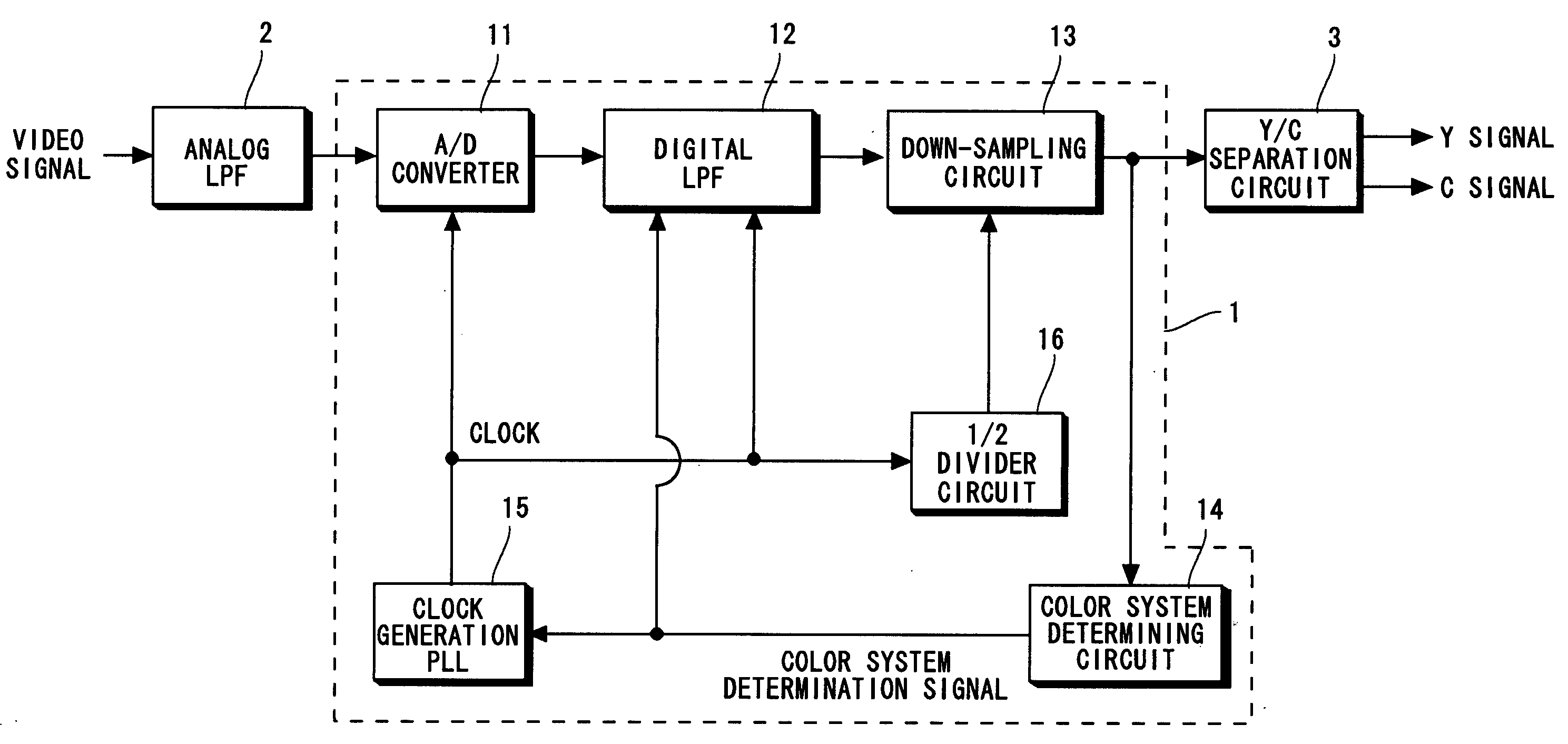
  • Over-sampling A/D converting circuit
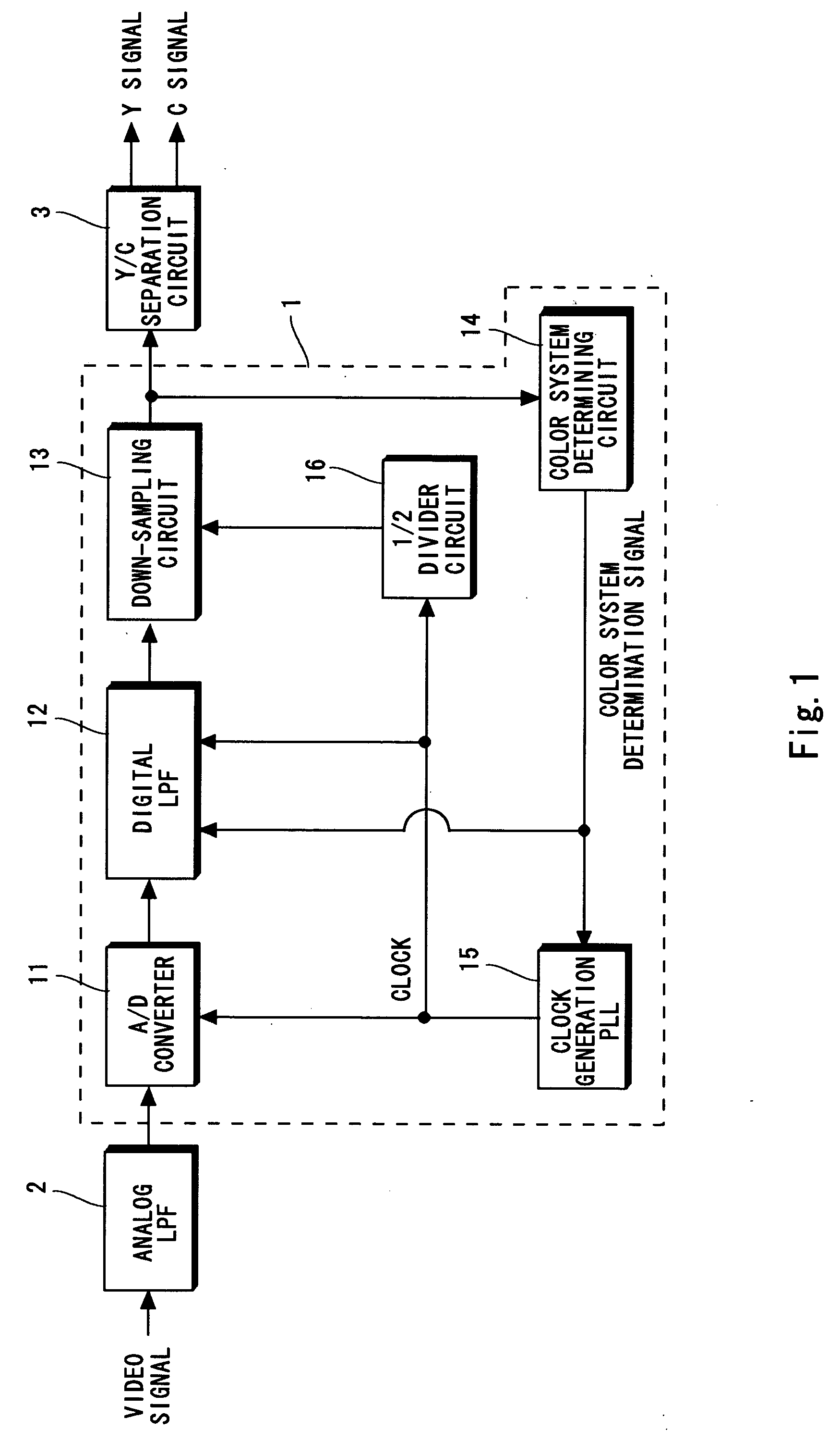
  • Over-sampling A/D converting circuit
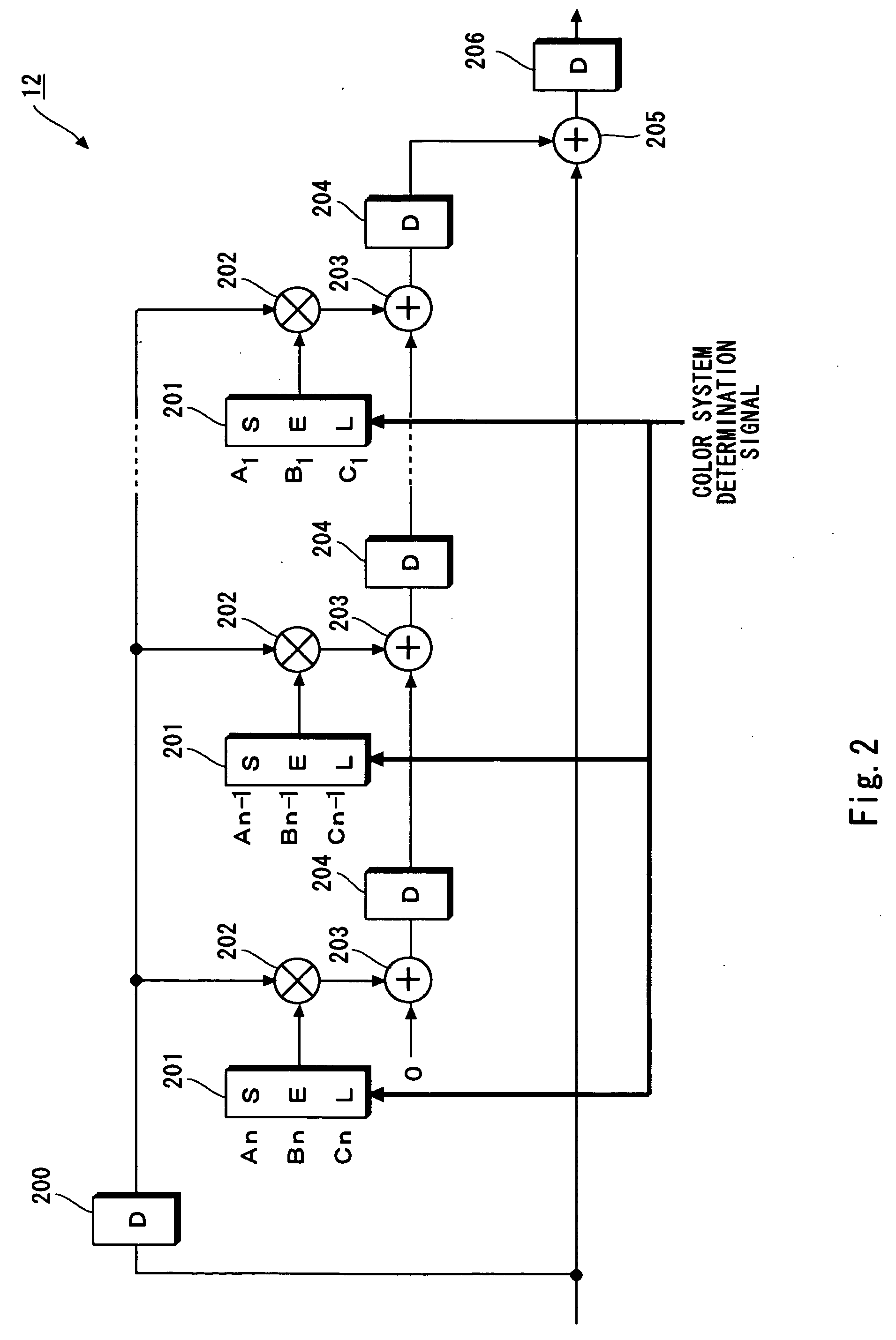
  • Over-sampling A/D converting circuit

Examples


first embodiment

[0029] Referring now to FIGS. 1 and 2, a video signal processing circuit and an A / D converting circuit according to a first embodiment of the present invention are described. A feature of this embodiment is that a filter factor of the LPF in the A / D converting circuit is changed depending on the color television system to obtain optimum filter characteristics.

[0030]FIG. 1 shows the configuration of the video signal processing circuit according to this embodiment. This video signal processing circuit is provided to, for example, a television receiver and adapted to convert radio wave received through an antenna into an RF signal and receive a video signal obtained by detecting a picture carrier.

[0031] The video signal processing circuit receivers a composite video signal (analog video signal) prepared by superimposing the Y signal and the C signal as shown in FIGS. 4 and 5 to convert the analog signal into a digital signal and separate the Y signal from the C signal. The signal is ...

second embodiment

[0048] Referring next to FIG. 3, a video signal processing circuit and an A / D converting circuit according to a second embodiment of the present invention are described. A feature of this embodiment is that an LPF of the A / D converting circuit is selected in accordance with a color television system to thereby obtain the optimum filter characteristics.

[0049]FIG. 3 shows the configuration of the video signal processing circuit according to this embodiment. The same components as those of FIG. 1 are denoted by like reference numerals, and their description is omitted if not necessary.

[0050] In this embodiment, in the over-sampling A / D converting circuit 1, digital LPFs 121, 122, and 123, and a selector 17 are provided in place of the digital LPF 12 of FIG. 1.

[0051] Different cut-off frequencies are set for the digital LPFs 121, 122, and 123, each of which is optimum for a corresponding color television system. In the illustrated example, the three digital LPFs are provided, but the...


PUM


Abstract

To provide an A / D converting circuit capable of improving an S / N ratio regardless of a color television system. An over-sampling A / D converting circuit according to an embodiment of the present invention includes: an A / D converter for over-sampling an analog video signal; a digital low-pass filter allowing passage of a signal component in a predetermined passing band out of the over-sampled signal; a down-sampling circuit for down-sampling the passed signal; and a color television system determining circuit for switching the passing band.

Description

BACKGROUND OF THE INVENTION [0001] 1. Field of the Invention [0002] The present invention relates to an over-sampling A / D converting circuit, in particular, an over-sampling A / D converting circuit for processing analog video signals. [0003] 2. Description of Related Art [0004] In recent years, television receivers or monitoring devices have advanced toward upsizing of their screens for displaying a picture. In such television receivers, a problem about a displayed image such as weak video noise comes to the surface albeit being ignorable on a small screen. To that end, a higher image quality is required. [0005] In general, a composite video signal as shown in FIG. 4 is input to the television receiver. As shown in FIG. 4, the composite video signal includes a video signal obtained by multiplexing a luminance signal (Y signal) with a chrominance signal (C signal), a burst signal used as a reference for the chrominance signal, and a sync signal for synchronizing signals. Further, the ...

Claims


Application Information

Patent Timeline
Patent Type & Authority Applications(United States)
IPC IPC(8): H03M1/12H04N9/64H04N5/14
CPCH04N9/64H04N9/642H04N9/78H04N5/14H03M1/12
Inventor TASHIRO, YASUNORI
Owner RENESAS ELECTRONICS CORP
Learn More