System and method for detecting objects and communicating information

a technology of object detection and communication information, applied in the field of radio locating tags, can solve the problems of large power consumption at the transmitter, inability to easily resolve fine distances or distinguish multiple tags simultaneously in the field, and requires a significant battery to supply the transmitted rf power, etc., to achieve the effect of light weight, low cost and small siz

Inactive Publication Date: 2006-07-06
TIME DOMAIN
View PDF22 Cites 90 Cited by
  • Summary
  • Abstract
  • Description
  • Claims
  • Application Information

AI Technical Summary

Benefits of technology

[0013] One advantage of the present invention is that the antenna and property varying components can be made very small, light weight, low cost and can be constructed so as to consume very little battery power, thus enabling operation for months or years on practical batteries, achieving operational lifetimes similar to battery operated watches and clocks.
[0014] Another advantage of the present invention is that the radar system can separate and select antennas utilizing relative return signal delay resulting from differences in range and thus accommodate multiple objects with reduced interference from non-selected objects. The multiple objects may even utilize a single pattern or family of patterns. The total capacity, or number of antenna devices that can be operated in a given area can be multiplied by this resolution factor.
[0015] A further advantage of the present invention is that multipath reflections do not cancel in the manner of narrow band Rayleigh fading so that it is relatively difficult to place an antenna in a location or configuration where it cannot be detected due to Rayleigh fading.
[0016] A further advantage of the present invention is that the distance to the antenna device can be determined very accurately, for example, to on the order of a wavelength of the nominal bandwidth of the probing radar. This may be one foot (30 cm) or so for a typical UWB radar with a 1 GHz bandwidth.
[0017] A further advantage is that the frequency or rate of change of the pattern is not critical, permitting very low cost reference oscillators and enabling low cost antenna devices.
[0018] A further advantage is that data may be encoded on the pattern to enable communication of such information as a serial number, a temperature measurement, an audio signal, external data, or accounting information as in a frequent shopper card, or personnel access information as in an entry identification tag, or other information as needed for the many potential uses for this invention.

Problems solved by technology

This system, however, utilizes a very strong RF probing field that requires very high gain antennas to be projected to significant distances, consumes considerable power at the transmitter, and cannot easily resolve fine distances or distinguish multiple tags simultaneously in the field.
This system, however, requires a significant battery to supply the transmitted RF power.
Each of these technologies has one or more requirements that limit its use in certain applications.

Method used


Image

  • System and method for detecting objects and communicating information
  • System and method for detecting objects and communicating information
  • System and method for detecting objects and communicating information

Examples


Embodiment Construction

[0076] Further features and advantages of the invention will become apparent in the following detailed description of the invention and its various embodiments. The first section is a brief overview of Ultra Wideband technology to help in the understanding of the present invention. Numerous features or embodiments of the present invention incorporate or depend on the Ultra Wideband technology described.

Ultra Wideband Technology Overview

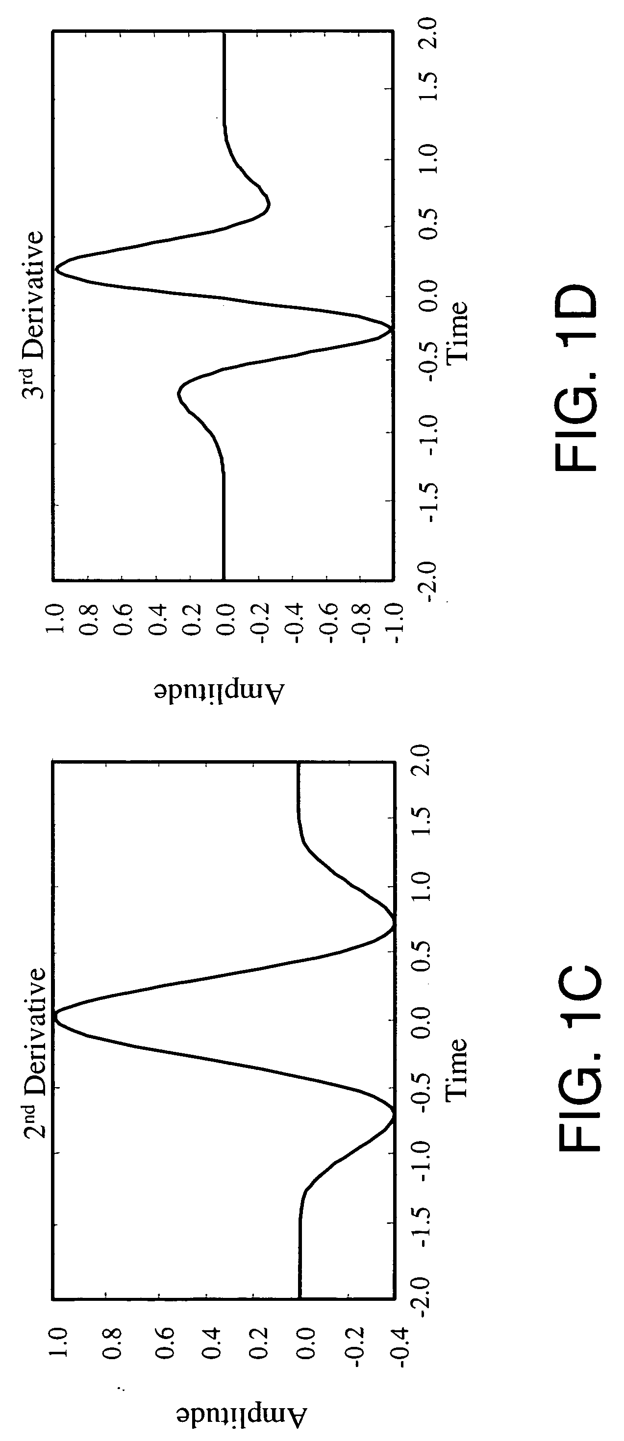
[0077] Ultra Wideband is an emerging RF technology with significant benefits in communications, radar, positioning and sensing applications. In 2002, the Federal Communications Commission (FCC) recognized these potential benefits to the consumer and issued the first rulemaking enabling the commercial sale and use of products based on Ultra Wideband technology in the United States of America. The FCC adopted a definition of Ultra Wideband to be a signal that occupies a fractional bandwidth of at least 0.25, or 500 MHz bandwidth at any center frequen...


PUM


Abstract

A system and method for locating objects and / or receiving data associated with an object. An antenna or similar device that can intercept or modify RF energy is caused to vary its properties in accordance with a predefined time sequence pattern that is associated with the object. The antenna device is located proximate to the object to be located. To locate the object, a wide band radar device is utilized to transmit a probe signal and receive and analyze the return signal to identify the predefined pattern and determine the range to the antenna and thus determine the range to the associated object. The time sequence pattern is optionally modulated by a data stream to convey data associated with the object.

Description

BACKGROUND OF THE INVENTION [0001] 1. Field of the invention [0002] The present invention relates to the field of radio locating tags, in particular, non-transmitting locating tags. [0003] 2. Related applications [0004] This application incorporates by reference Provisional Application 60 / 323,560 titled “UWB Reflective Tag System and Method,” filed Sep. 20, 2001. [0005] 3. Related Art [0006] RF tags for detecting and relaying information about an object have found wide application in industry and commerce. Applications for tags range from simply detecting the proximate presence of an object to relaying information, such as for personnel security access control or toll booth charging systems. [0007] One system in use transmits an RF microwave field strong enough to be directly rectified to supply power to a transmitter chip which in turn transmits information, such as a serial number, which is then received by the probing system. The serial number then, is used for tollbooth billing,...

Claims


Application Information

Patent Timeline
Patent Type & Authority Applications(United States)
IPC IPC(8): G08B13/14H04Q5/22
CPCG01S13/0209G01S13/756G01S13/765G06K7/10306
Inventor RICHARDS, JAMES L.FULLERTON, LARRY W.COWIE, IVAN A.
Owner TIME DOMAIN
Why Eureka
Try Eureka