
Roller seam welded body for exhaust gas treatment and process for producing the body

Inactive Publication Date: 2006-07-06
EMITEC GESELLSCHAFT FUR EMISSIONSTECHNOLOGIE MBH
View PDF15 Cites 9 Cited by
  • Summary
  • Abstract
  • Description
  • Claims
  • Application Information

AI Technical Summary

Benefits of technology

[0012] It is accordingly an object of the invention to provide a roller seam welded body for exhaust gas treatment and a process for producing the body, which overcome the hereinafore-mentioned disadvantages and technical problems of the heretofore-known devices and processes of this general type, in which the process for producing metallic bodies of this type for exhaust gas purification is inexpensive, simple, effective and reliable and is suitable for automation as far as possible, producing connections by joining which are distinguished by a particularly long service life, and in which the corresponding body for exhaust gas treatment can be configured variably and is versatile in use.
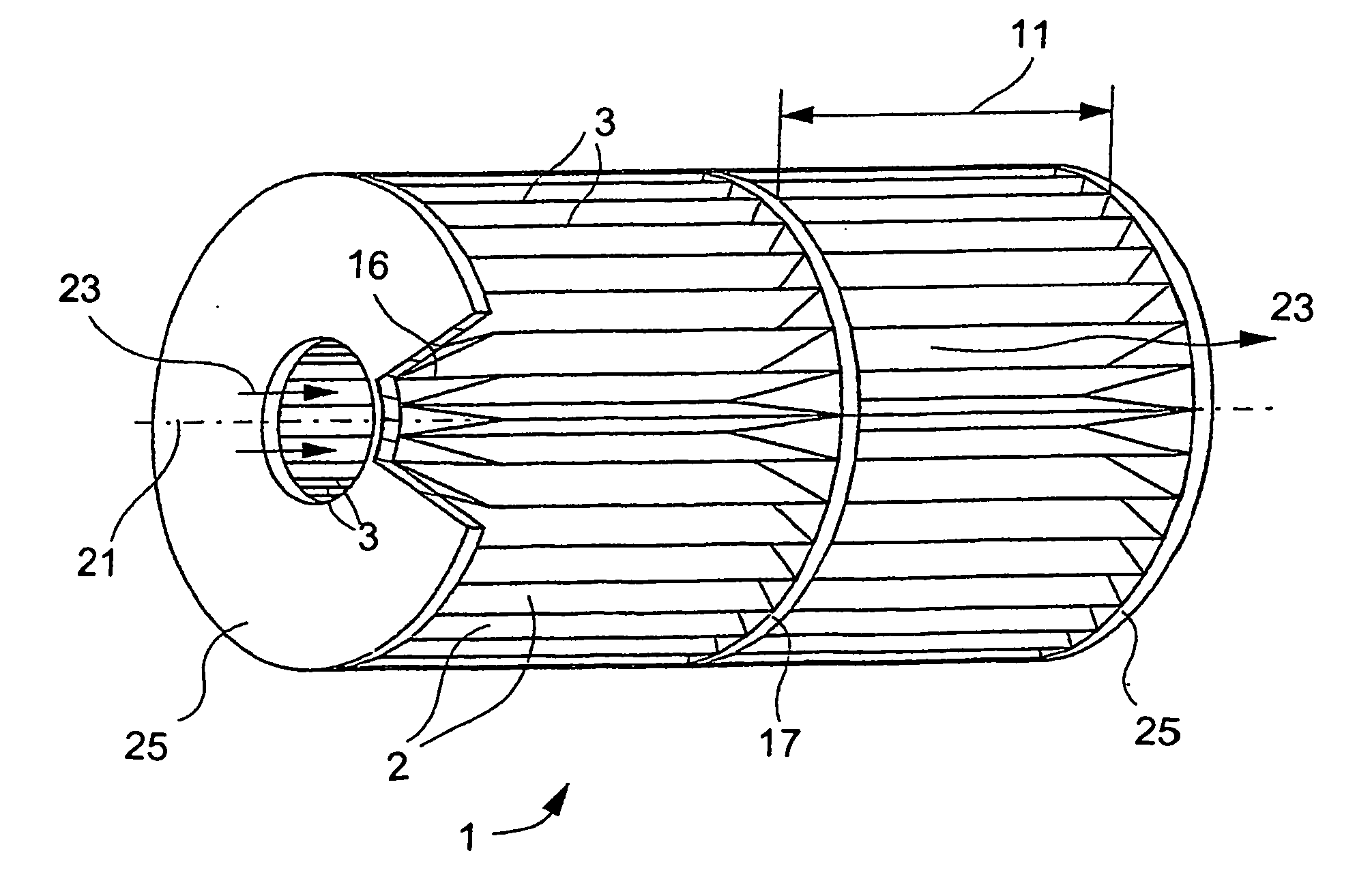
[0019] The use of this production process to connect the layers has proven particularly advantageous in particular with a view toward series production of these bodies. The process in which the two layers adjacent or lying on top of one another are passed through the rotating electrodes is surprisingly well able to withstand the high thermal and dynamic stresses, for example in the exhaust system of automobiles. It has also been established that even in the case of very thin metal foils which are connected to one another in this way, sealed weld seams can be produced in very short working cycles. As a result, it is possible to achieve in particular a cost benefit, which was unexpected in view of the additional material that is required for the overlap between the two layers. Roller seam welding is suitable in particular for connection regions which have a certain length, i.e. extend over a predetermined portion. This should generally amount to at least 5 cm, in particular at least 15 cm, and the work can be carried out at particularly low cost beyond a length of 25 cm. The roller seam welding makes do without filler. Furthermore, in many cases it is also possible to do without a step of cleaning the layers, since the introduction of the electrode force ensures that contact between the electrodes and / or the layers which is sufficient for the flow of current and the formation of the weld spot is already ensured to a considerable extent. Moreover, only an insignificant change in the microstructure of the layer adjacent the weld nugget can be established. Accordingly, the use of this manufacturing process offers numerous advantages and at the same time overcomes all of the technical problems listed in the introduction hereto at once. Moreover, the process can also be applied to each of the types of bodies mentioned in the introduction hereto.

Problems solved by technology

However, this need not necessarily be the case.

Method used


Image

  • Roller seam welded body for exhaust gas treatment and process for producing the body
  • Roller seam welded body for exhaust gas treatment and process for producing the body
  • Roller seam welded body for exhaust gas treatment and process for producing the body

Examples


Embodiment Construction

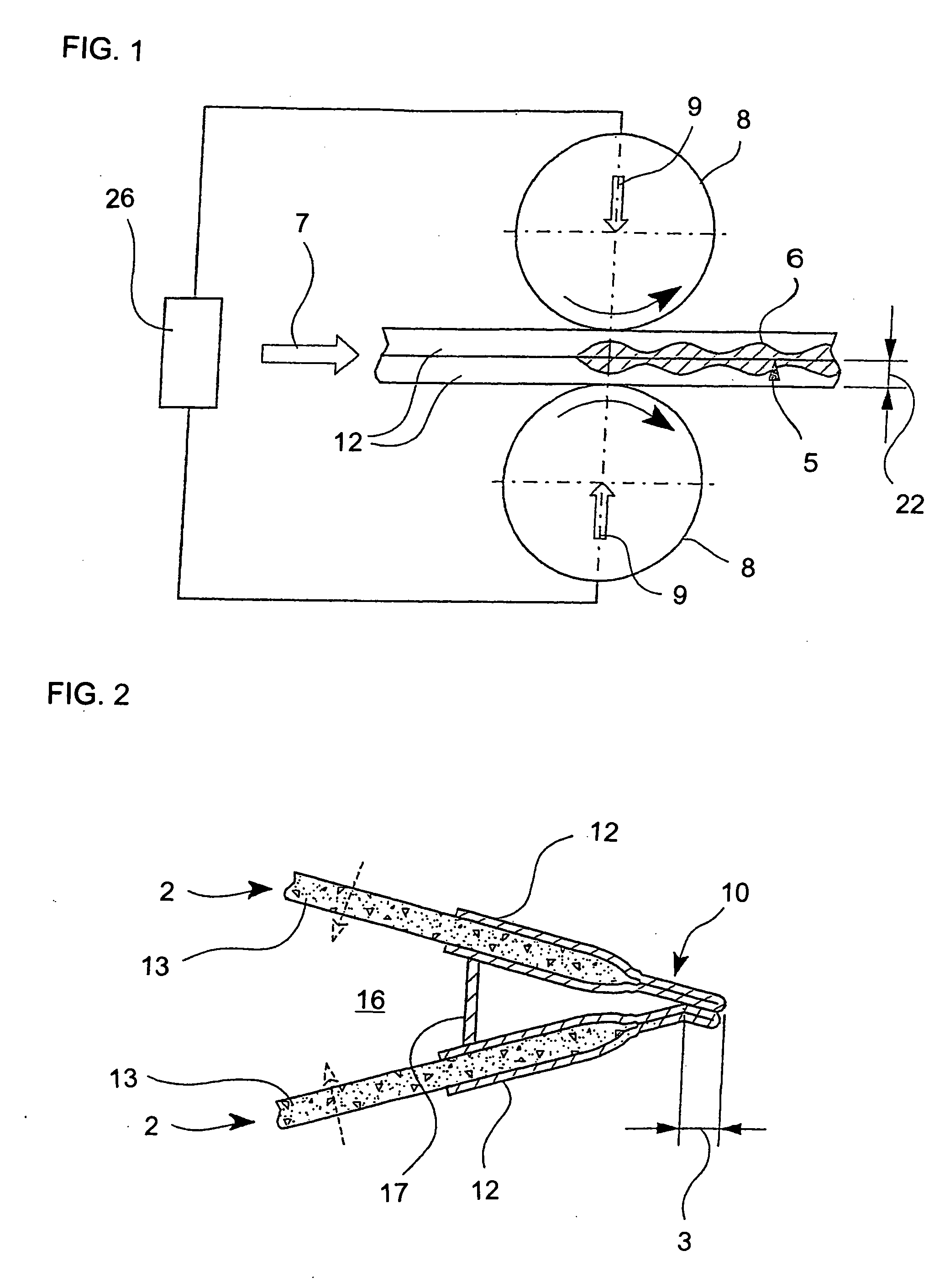
[0051] Referring now to the figures of the drawings in detail and first, particularly, to FIG. 1 thereof, there is seen a diagrammatic and schematic illustration of a sequence involved in the production process of roller seam welding, which is used in this case to produce a body for exhaust gas treatment. FIG. 1 illustrates two metallic foils 12 which are brought into contact with one another. The foils 12, while resting on top of one another, are passed at a feed rate 7 through two rotating electrodes 8. In the process, the two electrodes 8 press on the surface of the foils 12 with a force 9. The two electrodes 8 are connected to one another through a current source 26, with current flowing between the electrodes 8 and therefore also locally through the foils 12 with a predetermined frequency. The current leads to heating of the foils 12, so that they become at least partially molten. The foils 12 in this case have a thickness 22 which is, for example, in the range from 0.02 to 0.1...


PUM

PropertyMeasurementUnit
forceaaaaaaaaaa
forceaaaaaaaaaa
diameteraaaaaaaaaa

Abstract

A process for producing a body for exhaust gas treatment having a plurality of metallic layers, includes bringing the layers into contact with each other in a connection region. A connection is made by a roller seam welding process in such a way that the layers form passages through which a gas stream can flow. A corresponding body for exhaust gas treatment can especially be used as a filter or catalyst carrier body in the automobile industry.

Description

CROSS-REFERENCE TO RELATED APPLICATION [0001] This is a continuing application, under 35 U.S.C. §120, of copending International Application PCT / EP 2004 / 008560, filed Jul. 30, 2004, which designated the United States; this application also claims the priority, under 35 U.S.C. §119, of German Patent Application 103 37 265.2, filed Aug. 13, 2003; the prior applications are herewith incorporated by reference in their entirety.BACKGROUND OF THE INVENTION Field of the Invention [0002] The present invention relates to a process for producing a body for exhaust gas treatment, which has a plurality of metallic layers forming passages through which a gas stream can flow. Bodies of that type are used in particular for purifying the exhaust gases from mobile internal combustion engines, such as spark ignition or diesel engines. Primary application areas in this context are passenger automobiles as well as trucks and motorcycles. It is also known for such bodies to be used in exhaust systems of...

Claims


Application Information

Patent Timeline
Patent Type & Authority Applications(United States)
IPC IPC(8): B23K1/00B23K31/02B01J35/04B23K11/00B23K11/06F01N13/18
CPCB01J35/04B23K11/0026B23K11/06B23K11/065B23K2201/006B23K2201/04F01N13/1838F01N2330/02F01N2330/04F01N2330/12F01N2450/22B23K2101/006B23K2101/04B01J35/56
Inventor HIRTH, PETERBRUCK, ROLFHARIG, THOMAS
Owner EMITEC GESELLSCHAFT FUR EMISSIONSTECHNOLOGIE MBH
Learn More