
Dynamic mass transfer rapid response power conversion system

a technology of mass transfer and power conversion system, applied in the direction of clutches, couplings, fluid couplings, etc., can solve the problems of difficult or largely unworkable primary power sources utilizing fossil fuels for energy production, difficult internal combustion engines, etc., and achieve the effect of rapid response and facilitate combustion

Active Publication Date: 2006-07-06
SARCOS LC
View PDF24 Cites 4 Cited by
  • Summary
  • Abstract
  • Description
  • Claims
  • Application Information

AI Technical Summary

Benefits of technology

[0014] It is a further object of some of the exemplary embodiments of the present invention to operate the energy transfer component independent of the rapid response component, thus allowing the rapid response component to optimize the extraction of energy from the internal combustion engine.
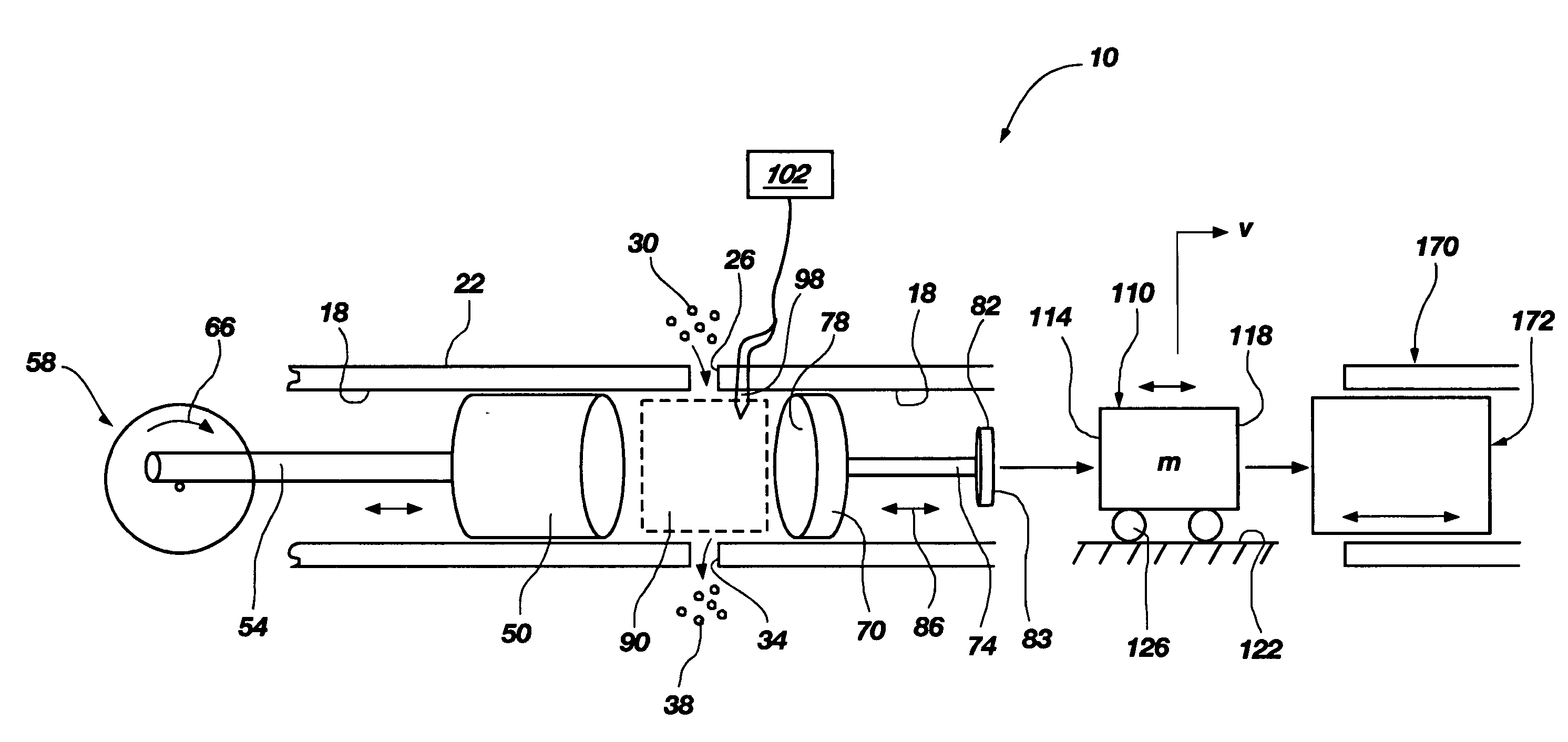
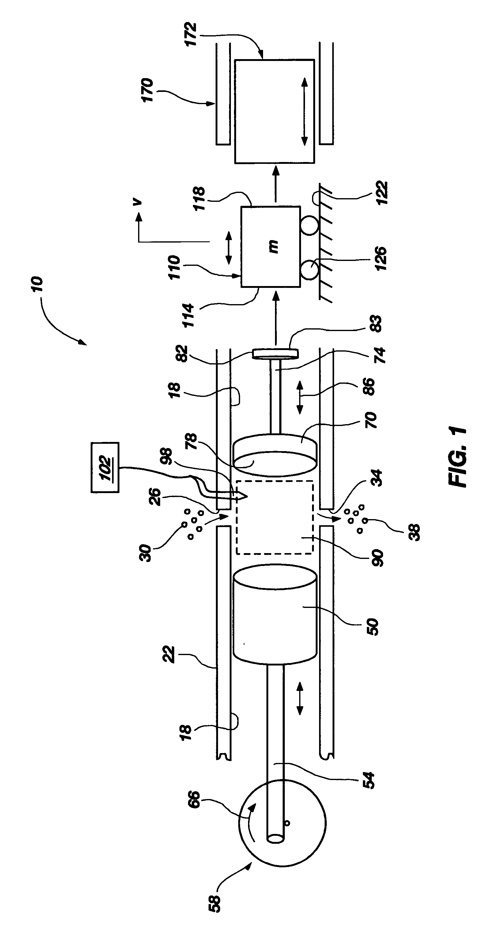
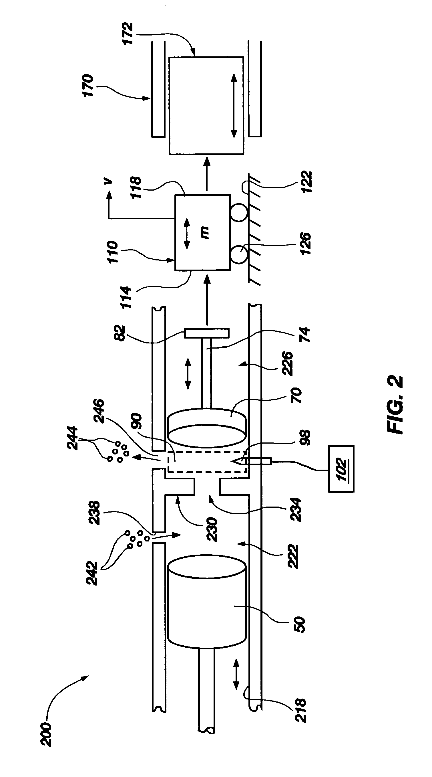
[0018] To achieve the foregoing objects, and in accordance with the invention as embodied and broadly described herein, the present invention features a rapid fire rapid response power conversion system comprising (a) a chamber having at least one fluid port configured to supply combustible fluid to the chamber, and an out-take port; (b) a local compressor having a piston for supplying compressed combustible fluid to the chamber, wherein the piston and the at least one fluid port are configured to selectively provide a variable pressure to the chamber and to at least partially facilitate combustion therein; (c) a controller for initiating and controlling a combustion of the fluid in a combustion portion of the chamber to generate energy; (d) a rapid response component in fluid communication with the chamber and situated adjacent the combustion portion of the chamber, wherein the rapid response component is configured to draw an optimized portion of the energy generated from the combustion and to convert this optimized portion of energy into kinetic energy; and (e) a dynamic mass structure situated between the rapid response component and an energy transfer component and allowing the rapid response component and the energy transfer component to be independent of one another, wherein the dynamic mass structure is configured to receive and store all or substantially all of the kinetic energy from the rapid response component upon being acted upon by the rapid response component, wherein the dynamic mass structure is displaced some distance and at some velocity until it impacts the energy transfer component, thereby transferring substantially all of the kinetic energy stored therein into the energy transfer component. The transfer of stored kinetic energy into the energy transfer component by the dynamic mass structure effectively actuates the energy transfer component to perform work used to power the device or system operable with the energy transfer component. In another embodiment, the present invention rapid response power conversion system would comprise a remote compressor rather than a local compressor.

Problems solved by technology

While primary power sources have been successfully used to perform the several functions described above, they have not been successfully used independently in many applications because of their relatively slow response characteristics.
Although large amounts of energy are contained within a single drop of fuel, internal combustion engines are particularly problematic in powering small devices, and particularly robotic devices and other similar systems that utilize a feedback loop to make real time adjustments in the movement of the mechanical structure being driven.
Primary power sources utilizing fossil fuels for energy production have proved difficult or largely unworkable in these environments.
Setting aside impedance factors, the engine cannot reach the desired change in a very rapid fashion due to several inertial forces internal to the engine and the nature of the combustion process.
Moreover, if it is attempted to operate the engine repeatedly in a rapid cycle from 0 to 7000 rpm and back to 0 rpm, the response time of the engine slows even further as the engine attempts to respond to the cyclic signal.
Heavy equipment is generally powered by an internal combustion engine, usually a diesel engine, which supplies ample power for the maneuvering and driving of the equipment, but is incapable of meeting the energy response requirements of the various functional components, such as the bucket or backhoe.
However, this versatility comes at a cost.
In order for a system to be energetically autonomous and be capable of rapid, precise control, more component parts or structures are required, thus increasing the weight of the system and its operating costs.
However, in order to use electric power in a system without tethering the system to the power grid, the system must be configured to use energy storage devices such as batteries, which can be very large and heavy.
As modern technology moves into miniaturization of devices, the extra weight and volume of the power source and its attendant conversion hardware are becoming major hurdles against meaningful progress.
The complications inherent in using a primary power source to power a rapid response source become increasing problematic in applications such as robotics.
To date, however, technology has struggled to realize this combination of rapid response, minimal weight, effective control, and autonomy of operation.

Method used


Image

  • Dynamic mass transfer rapid response power conversion system
  • Dynamic mass transfer rapid response power conversion system
  • Dynamic mass transfer rapid response power conversion system

Examples


Embodiment Construction

[0030] The following detailed description of exemplary embodiments of the invention makes reference to the accompanying drawings, which form a part hereof and in which are shown, by way of illustration, exemplary embodiments in which the invention may be practiced. While these exemplary embodiments are described in sufficient detail to enable those skilled in the art practice the invention, it should be understood that other embodiments may be realized and that various changes to the invention may be made without departing from the spirit and scope of the present invention. Thus, the following more detailed description of the embodiments of the present invention, as represented in FIGS. 1 through 8, is not intended to limit the scope of the invention, as claimed, but is presented for purposes of illustration only and not limitation to describe the features and characteristics of the present invention, to set forth the best mode of operation of the invention, and to sufficiently enab...


PUM


Abstract

The present invention features a rapid fire rapid response power conversion system comprising (a) a chamber having at least one fluid port configured to supply combustible fluid to the chamber, and an out-take port; (b) a compressor for supplying compressed combustible fuel to the chamber at a variable pressure to at least partially facilitate combustion therein; (c) a controller for initiating and controlling a combustion of the combustible fluid in a combustion portion of the chamber to generate energy; (d) a rapid response component in fluid communication with the chamber and situated adjacent the combustion portion of the chamber, wherein the rapid response component is configured to draw an optimized portion of the energy generated from the combustion and to convert this optimized portion of energy into kinetic energy; and (e) a dynamic mass structure situated between the rapid response component and an energy transfer component and allowing the rapid response component and the energy transfer component to be independent of one another, wherein the dynamic mass structure is configured to receive and store the kinetic energy from the rapid response component upon being acted upon by the rapid response component, wherein the dynamic mass structure is displaced a pre-determined distance and at a given velocity such that it is caused to impact the energy transfer component, thereby transferring substantially all of the kinetic energy stored therein into the energy transfer component. The transfer of stored kinetic energy into the energy transfer component by the dynamic mass structure effectively causes the energy transfer component to displace, wherein the displacement is used to perform work used to power the device or system operable with the energy transfer component.

Description

[0001] This application claims priority to U.S. Provisional Patent Application No. 60 / 632,866, filed Dec. 2, 2004 in the United States Patent and Trademark Office, and entitled, “Dynamic Mass Transfer Rapid Response Power Conversion System,” which application is incorporated by reference in its entirety herein.FIELD OF THE INVENTION [0002] The present invention relates generally to power conversion systems that utilize an internal combustion engine to generate energy from its combustion cycles and a power conversion device configured to extract the generated energy and convert it into usable energy or work. More specifically, the present invention relates to a dynamic mass transfer rapid response power conversion system and method for rapidly extracting and converting the energy produced by an internal combustion engine, wherein the internal combustion engine operates independent of an energy transfer component used to convert the generated energy to usable power, thus allowing the ...

Claims


Application Information

Patent Timeline
Patent Type & Authority Applications(United States)
IPC IPC(8): F16D31/02
CPCF02B63/041F02B71/04
Inventor JACOBSEN, STEPHEN C.OLIVIER, MARC
Owner SARCOS LC
Learn More